INSTANT DOWNLOAD (add to cart)
5,000+ pages, bookmarked, Searchable, Printable, high quality PDF
9-91370_EN – EXCAVATOR WX95, WX125 SERVICE MANUAL.pdf
9-91360_FR – PELLE WX95, WX125 MANUEL DE SERVICE.pdf
9-91370 EN – WX95, WX125 Excavator Service Manual.pdf
9-91380_DE – BAGGER WX95, WX125 WERKSTATTHANDBUCH.pdf
9-93260_IT – ESCAVATORE WX95, WX125 MANUALE ISTRUZIONI PER LE RIPARAZIONI.pdf
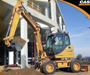
Complete digital official shop manual contains service, maintenance, and troubleshooting information for the Case WX95, WX125 Excavator. Diagnostic and repair procedures are covered in great detail to repair, maintain, rebuild, refurbish or restore your Case WX95, WX125 Excavator like a professional mechanic in local service/repair workshop. This cost-effective quality manual is 100% complete and intact as should be without any missing pages. It is the same factory shop manual used by dealers that guaranteed to be fully functional to save your precious time.
This manual for Case WX95, WX125 Excavator is divided into different sections. Each section covers a specific component or system and, in addition to the standard service procedures, includes disassembling, inspecting, and assembling instructions. A table of contents is placed at the beginning of each section. Pages are easily found by category, and each page is expandable for great detail. It is in the cross-platform PDF document format so that it works like a charm on all kinds of devices. You do not need to be skilled with a computer to use the manual.
EXCERPT:
AXLES
OPERATIONAL PRINCIPLE
STEERING AXLES: FRONT AND REAR
The steering effect is obtained with an hydraulic cylinder acting on the two articulation boxes (right and left) directing them according to the flywheel rotation
sense.
The swinging effect is obtained by two supports complete of bushings, mounted on the central housing of the axle in turn secured to the lower frame of the machine.
The axles consist mainly of:
• Axle body
• Steering control cylinder
• Lateral reduction units
• Differential and pinion (in the axle body)
• Braking unit (in the axle body)
Those components are contained both in the front and back axle. Namely the only difference between both axles is that the rear axle carries:
• The outer negative hydraulic brake.
STEERING FRONT AXLE
…
BRAKING UNIT
The braking action is hydraulically actuated in both axles through wet discs.
The service brake circuit is actuated by the action exercised on the brake valve. The latter sends pressurised hydraulic oil (70 bar) to the piston of the front and rear axle. These pistons, after overcoming the reaction of the springs, keeping the drive plate in rest condition, ensure that the discs are pressed one against the other, thus providing the braking action.
The service brake circuit can be applied, while the machine is standing, by pressing a switch located on the steering column, that controls electrically, the brake valve; the braking action occurs, under these conditions, in a non modulated manner and allows an optimised stability during digging operations. The application of the work brake is signalled by an indicator located in correspondence with the actuating switch.
STEERING CASE AND LATERAL REDUCTION UNIT
The final drive is of a planetary type and its function is to reduce in an appropriate manner, the r.p.m. of the drive wheels with respect to the r.p.m. output of the
differential.
The reduction unit is composed of a toothed hub, three planetary gears and a solar gear splined on the end of the axle shaft.
The reduction unit is fitted in the cover on its turn fitted on the wheel hub.
This hub is located in the steering case, which thanks to the articulations (and to the steering cylinder movement) enables the wheels steering.
…
INSTANT DOWNLOAD (add to cart)

