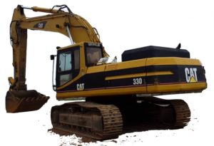
Complete workshop & service manual with electrical wiring diagrams for Caterpillar 330, 330L & 330 LN Excavators. It’s the same service manual used by dealers that guaranteed to be fully functional and intact without any missing page.
This Caterpillar 330, 330L & 330 LN Excavators service & repair manual (including maintenance, overhaul, disassembling & assembling, adjustment, tune-up, operation, inspecting, diagnostic & troubleshooting…) is divided into different sections. Each section covers a specific component or system with detailed illustrations. A table of contents is placed at the beginning of each section. Pages are easily found by category, and each page is expandable for great detail. The printer-ready PDF documents work like a charm on all kinds of devices.
MANUAL LIST:
SENR5497 – Schematic (330 Excavators Hydraulic System).pdf
SENR5496 – Testing & Adjusting (330, 330L & 330 LN Excavators Hydraulic & Electronic Sys)
SENR5498 – Disassembly & Assembly (330, 330 L & 330 LN Excavators Machine Systems)
SENR5499 – Schematic (330 Excavator Electrical System)
SENR5557 – Disassembly & Assembly (3306 Engine Supplement for 330, 330L, & 330 LN Excavators)
SENR5495 – Systems Operation (330, 330 L & 330 LN Excavators Hydraulic System).pdf
SENR5493 – Specifications (330, 330L & 330LN Excavators Hydraulic System)
EXCERPT:
a. Move the control levers for the boom, bucket, stick and swing through their full travel strokes. This will relieve any pressure that may be present in the pilot system.
b. Slowly loosen the air breather cap on the hydraulic oil tank to release the pressure.
c. Tighten the air breather cap on the hydraulic oil tank.
d. Tighten the air breather cap on the hydraulic oil tank.
e. The pressure in the hydraulic system has now been released. Lines and components can now be removed.
9. Disconnect four hose assemblies (5) for the stick cylinder. Put plugs in the ends of the hose assemblies to keep dirt and debris out of the hydraulic system. Disconnect wiring harness (6) for the boom lights.
10. Remove hand rail (7) from the machine. This will provide the necessary clearance for removal of the pin assembly which holds the boom to the main frame of the machine.
11. Remove pin assembly retaining bolt (9) and the washer that holds pin assembly (8) in place.
…
