INSTANT DOWNLOAD
ADD TO CART
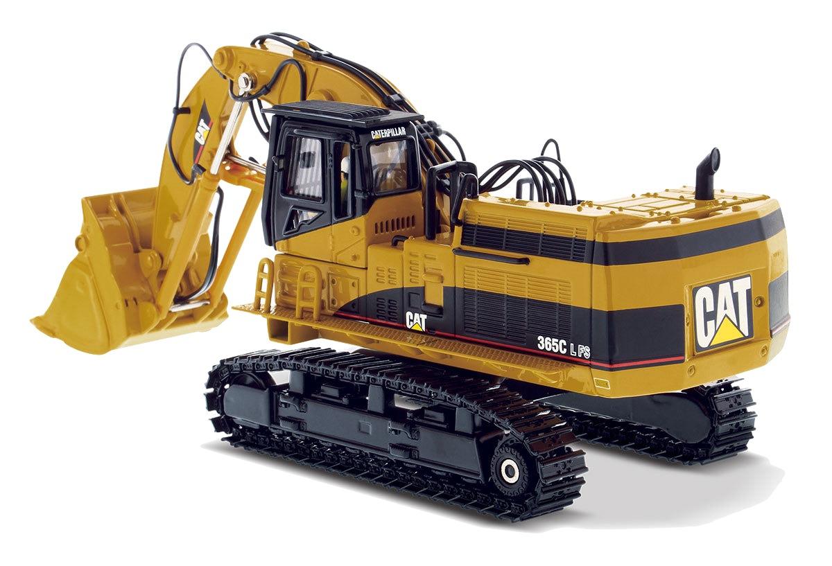
Complete workshop & service manual with electrical wiring diagrams for Caterpillar 365C Excavator, 365C Material Handler and 365C Front Shovel. It’s the same service manual used by dealers that guaranteed to be fully functional and intact without any missing page.
This Caterpillar 365C Excavator/Material Handler/Front Shovel service & repair manual (including maintenance, overhaul, disassembling & assembling, adjustment, tune-up, operation, inspecting, diagnostic & troubleshooting…) is divided into different sections. Each section covers a specific component or system with detailed illustrations. A table of contents is placed at the beginning of each section. Pages are easily found by category, and each page is expandable for great detail. The printer-ready PDF documents work like a charm on all kinds of devices.
MANUAL LIST:
RENR8616 – Disassembly and Assembly (365C Excavator Machine Systems)
KENR8656 – Schematic (CD700 AccuGrade Wiring for 365C & 385C Excavator Electrical System)
RENR7047 – Schematic (365C Excavators Hydraulic System (Attachment) Medium Pressure Circuit)
RENR7057 – Schematic (365C and 385C Excavators and 385C MHPU Electrical Schematic (Attachment) Medium Pressure)
RENR7062 – Schematic (365C Excavators Hydraulic System (Attachment) Boom Lowering Control Valve)
RENR7063 – Schematic (365C Excavators Hydraulic System (Attachment) Stick Lowering Control Valve)
RENR7064 – Schematic (365C Excavators Hydraulic System (Attachment) Fine Filtration)
RENR7065 – Schematic (365C Excavators Hydraulic System (Attachment) One Way Flow)
RENR7066 – Schematic (365C Excavators Hydraulic System (Attachment) Combined Function)
RENR7067 – Schematic (365C Excavators Hydraulic System (Attachment) Counterweight Removal)
RENR7068 – Schematic (365C Excavators Hydraulic System (Attachment) Smart Boom with Boom Lowering Control Valve)
RENR7215 – Schematic (365C Excavators Hydraulic System (Attachment) Smart Boom with Stick Lowering Control Valve)
RENR7216 – Schematic (365C Excavators Hydraulic System (Attachment) Reverse Fan)
RENR7303 – Specifications (365C Excavator, 365C Material Handler and 365C Front Shovel Machine System)
RENR7304 – Systems Operation (365C Excavator Hydraulic System)
RENR7305 – Testing and Adjusting (365C Excavator Hydraulic System)
RENR7306 – Schematic (365C Excavator Hydraulic System)
RENR7307 – Schematic (365C Excavator and 365C Front Shovel Electrical System)
RENR7328 – Specifications (345C, 365C and 385C Excavators Air Conditioning and Heating)
RENR7328 – Systems Operation (345C, 365C and 385C Excavators Air Conditioning and Heating)
RENR7328 – Testing and Adjusting (345C, 365C and 385C Excavators Air Conditioning and Heating)
RENR8067 – Systems Operation (365C & 385C Excavators and 365C MHPU and 385C MHPU Mobile Hydraulic Power Units Machine Electronic Control System)
RENR8067 – Testing & Adjusting (365C & 385C Excavators and 365C MHPU and 385C MHPU Mobile Hydraulic Power Units Machine Electronic Control System)
RENR8067 – Troubleshooting (365C & 385C Excavators and 365C MHPU and 385C MHPU Mobile Hydraulic Power Units Machine Electronic Control System)
RENR8615 – Disassembly and Assembly (365C Excavator Engine Supplement)
…
EXCERPT:
7. Install pinion (31) in swing drive housing (16) .
a. Apply Tooling (F) on the inside diameter of swing drive housing (16) .
b. Lower the temperature of pinion (31) .
c. Attach Tooling (E) and a suitable lifting device to pinion (31) .
d. Install the pinion (31) into swing drive housing (16) . Bearing (34) must be within the bore of the swing drive housing.
e. Remove Tooling (E) and the lifting device from pinion (31) . Attach the tooling and the lifting device to the swing drive housing.
f. Lift the swing drive vertically. Use a hammer and a suitable punch to align bearing (34) in the lower bore of the swing drive housing. When the bearing is properly aligned in the bore, shaft assembly (31) will drop into the proper position within the swing drive housing.
…
