INSTANT DOWNLOAD
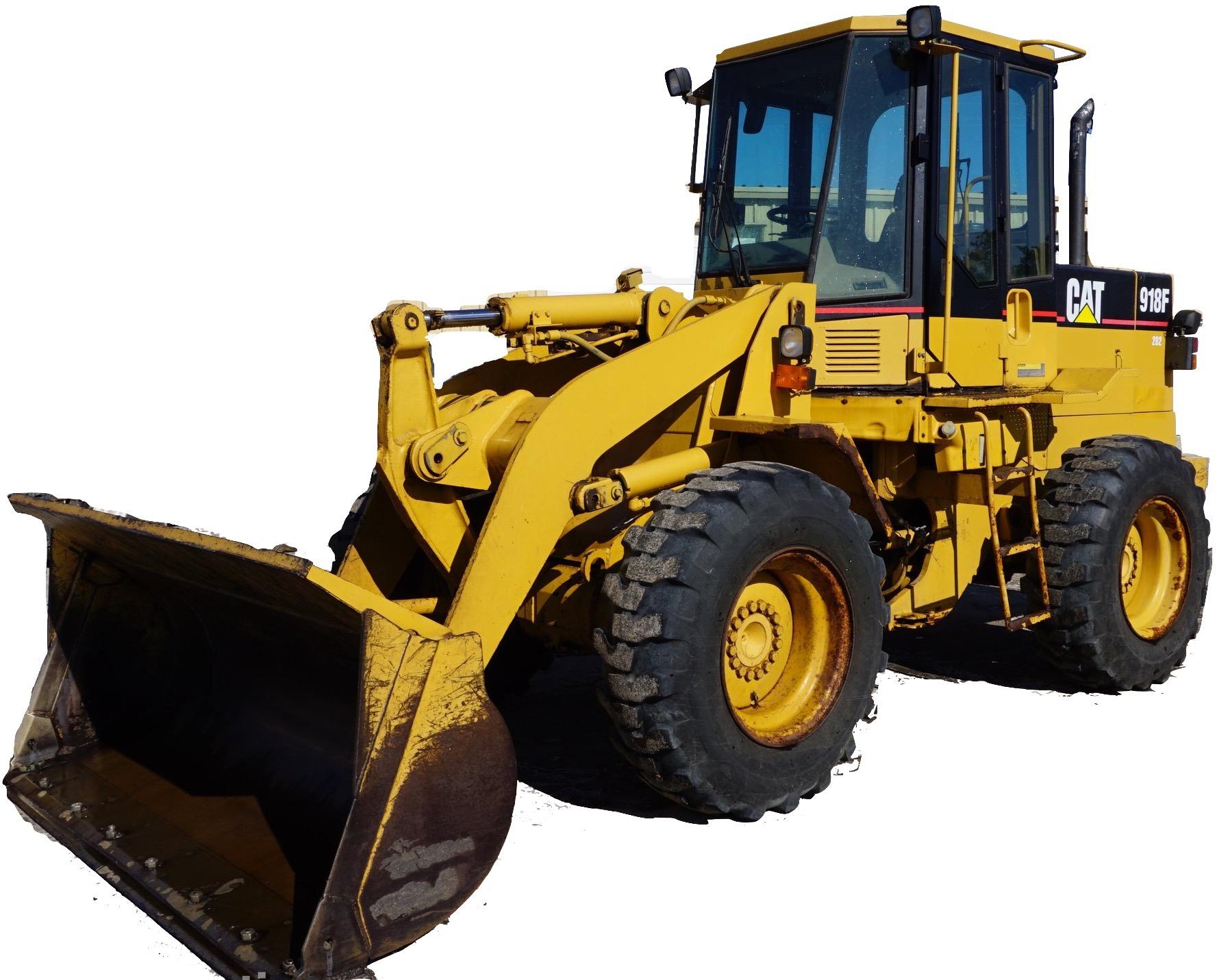
Complete workshop & service manual with electrical wiring diagrams for Caterpillar 918F Wheel Loaders. It’s the same service manual used by dealers that guaranteed to be fully functional and intact without any missing page.
This Caterpillar 918F Wheel Loaders service & repair manual (including maintenance, overhaul, disassembling & assembling, adjustment, tune-up, operation, inspecting, diagnostic & troubleshooting…) is divided into different sections. Each section covers a specific component or system with detailed illustrations. A table of contents is placed at the beginning of each section. Pages are easily found by category, and each page is expandable for great detail. The printer-ready PDF documents work like a charm on all kinds of devices.
MANUAL LIST:
SENR5571 – Disassembly & Assembly (SUPPLEMENT FOR IT18F INTEGRATED TOOLCARRIER & 918F WHEEL LOADER)
SENR5763 – Specifications (918F WHEEL LOADER POWER TRAIN)
SENR5766 – Disassembly & Assembly (918F WHEEL LOADER POWER TRAIN)
SENR5767 – Specifications (918F WHEEL LOADER STEERING SYSTEM)
SENR5768 – Systems Operation (918F WHEEL LOADER STEERING SYSTEM)
SENR5769 – Specifications (918F WHEEL LOADER BRAKE SYSTEM)
SENR5771 – Specifications (918F WHEEL LOADER HYDRAULIC SYSTEM)
SENR5773 – Schematic (918F Wheel Loader Hydraulic System)
SENR5774 – Disassembly & Assembly (918F WHEEL LOADER MACHINE SYSTEMS)
SENR5775 – Schematic (918F Wheel Loader Electrical System)
SENR5764 – Systems Operation (918F WHEEL LOADER POWER TRAIN).pdf
SENR5764 – Testing & Adjusting (918F WHEEL LOADER POWER TRAIN).pdf
SENR5770 – Systems Operation (918F WHEEL LOADER BRAKE SYSTEM).pdf
SENR5770 – Testing And Adjusting (918F WHEEL LOADER BRAKE SYSTEM).pdf
SENR5772 – Systems Operation (918F WHEEL LOADER HYDRAULIC SYSTEM).pdf
SENR5772 – Testing & Adjusting (918F WHEEL LOADER HYDRAULIC SYSTEM).pdf
…
EXCERPT:
Spools in transmission control valve (2) send oil to engage the correct clutches for the speed and direction selected. To make the machine move, one directional clutch (FORWARD LOW, FORWARD HIGH, or REVERSE) and one speed clutch (FIRST, SECOND, or THIRD) must be engaged. Return oil from the control valve can enter the torque converter circuit through converter back flow check valve (4) [part of transmission control valve (2)]. Converter back flow check valve (4) prevents higher pressure from the torque converter charging circuit from entering control valve (2) when the control valve pressure is low during a shift.
…
