INSTANT DOWNLOAD (add to cart)

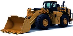
Complete workshop & service manual with electrical wiring diagrams for Caterpillar 988K Wheel Loader. It’s the same service manual used by dealers that guaranteed to be fully functional and intact without any missing page.
Caterpillar 988K Wheel Loader service & repair manual (including maintenance, overhaul, disassembling & assembling, adjustment, tune-up, operation, inspecting, diagnostic & troubleshooting…) is divided into different sections. Each section covers a specific component or system with detailed illustrations. A table of contents is placed at the beginning of each section. Pages are easily found by category, and each page is expandable for great detail. The printer-ready PDF documents work like a charm on all kinds of devices.
2,006 pages, bookmarked, Searchable, Printable, high quality PDF
FILE LIST:
KENR6486 – Disassembly and Assembly (836K Landfill Compactor, 834K Wheel Dozer and 988K Wheel Loader C18 Engine Supplement)
KENR6487 – Specifications (988K Wheel Loader Systems)
KENR6488 – Systems Operation (988K Wheel Loader)
KENR6488 – Testing and Adjusting (988K Wheel Loader)
KENR6490 – Disassembly and Assembly (836K Landfill Compactor, 834K Wheel Dozer and 988K Wheel Loader Power Train)
KENR6720 – Disassembly and Assembly (988K Wheel Loader, 834K Wheel Dozer and 836K Compactor Machine Systems)
RENR5397 – Specifications (988H, 988K, 990H, 990K, 992G, 992K, 993K, and 994K Wheel Loaders, and 854K Wheel Dozers Automatic Lubrication System (Hydraulic Actuated System)
RENR5397 – Systems Operation (988H, 988K, 990H, 990K, 992G, 992K, 993K, and 994K Wheel Loaders, and 854K Wheel Dozers Automatic Lubrication System (Hydraulic Actuated System)
RENR5397 – Testing and Adjusting (988H, 988K, 990H, 990K, 992G, 992K, 993K, and 994K Wheel Loaders, and 854K Wheel Dozers Automatic Lubrication System (Hydraulic Actuated System)
UENR3228 – Schematic (988K Wheel Loader Hydraulic System).pdf
UENR3875 – Schematic (988K Wheel Loader Electrical System).pdf
UENR7640 – Schematic (988K Wheel Loader (Steel Mill Option) Electrical System).pdf
EXCERPT:
Brake Accumulator
(1) Nitrogen charging valve. (2) Accumulator. (3) Nitrogen gas charge. (4) Piston. (5) Seal kit. (6) Pressure oil chamber. (7) Outlet to the service brake control valve.
Piston (4) moves up and down inside the bore of each accumulator (2). Nitrogen gas charge (3) has a charge of approximately 5520 kPa (800 psi). Each accumulator is charged with nitrogen through charging valve (1).
Oil enters pressure oil chamber (6) from the brake pump. The oil reaches the pressure oil chamber through outlet port (7). The oil pushes piston (4) upward. The pressure of the oil compresses the nitrogen gas.
When the pressure in the accumulator reaches approximately 14973 ± 345 kPa (2172 ± 50 psi) for the 834K and the 988K or when the accumulator reaches approximately 14485 ± 345 kPa (2100 ± 50 psi) for the 836K, the supply of oil is stopped. When either brake pedal is pushed, oil from pressure oil chamber (6) flows out of port (7) to the service brake control valve. This action applies the service brakes.
…
