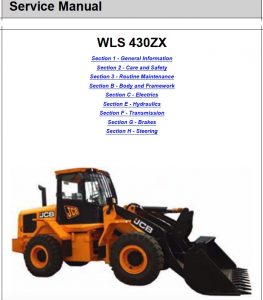
Pages from 9813-1050 – JCB 430ZX Wheeled Loader Shovel Service Manual
Complete workshop & service manual with electrical wiring diagrams for JCB Wheeled Loader 410, 412, 415, 420, 425, 430, 430Z, 430ZX. It’s the same service manual used by dealers that guaranteed to be fully functional and intact without any missing page.
This JCB Wheeled Loader 410, 412, 415, 420, 425, 430, 430Z, 430ZX service & repair manual (including maintenance, overhaul, disassembling & assembling, adjustment, tune-up, operation, inspecting, diagnostic & troubleshooting…) is divided into different sections. Each section covers a specific component or system with detailed illustrations. A table of contents is placed at the beginning of each section. Pages are easily found by category, and each page is expandable for great detail. The printer-ready PDF documents work like a charm on all kinds of devices.
FILELIST:
550-42385 – JCB 430Z Wheeled Loader Shovel Service Manual.pdf
9803-4100 – JCB 410, 412, 415, 420, 425, 430 Wheeled Loader Service Manual.pdf
9813-1050 – JCB 430ZX Wheeled Loader Shovel Service Manual.pdf
EXCERPT:
Service Manual
WLS 430ZX
Section 1 – General Information
Section 2 – Care and Safety
Section 3 – Routine Maintenance
Section B – Body and Framework
Section C – Electrics
Section E – Hydraulics
Section F – Transmission
Section G – Brakes
Section H – Steering
…
Cooling-Pack
Introduction
This is a combination pack, which supplies all the necessary cooling functions for the machines components with the exception of the ACU. (Most machines have air conditioning, but it is optional. Its installation or not does not make a difference to the function of the main cooling – pack.)
When viewed from the engine side A, the individual sections of the cooling-pack are:
– 1 Turbo Intercooler.
– 2 Transmission Oil Cooling.
– 3 Engine Coolant Radiator.
– 4 Hydraulic Oil Cooling.
The top and bottom holding-plates B and C hold the cooling-pack sections together.
Remove the section bolts 5 and 6, to remove and replace a single section. K Removal and Installation ( T B-16))
Fig 22.
7 Coolant drain plug.
8 The cooling-packs lower mounting points.
…