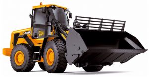
Pages from 9803-4160-17 – JCB 426, 435, 436, 446 Wheeled Loading Shovel Service Manual
Complete workshop & service manual with electrical wiring diagrams for JCB 426, 435, 436, 446 Wheeled Loading Shovel. It’s the same service manual used by dealers that guaranteed to be fully functional and intact without any missing page.
This JCB 426, 435, 436, 446 Wheeled Loading Shovel service & repair manual (including maintenance, overhaul, disassembling & assembling, adjustment, tune-up, operation, inspecting, diagnostic & troubleshooting…) is divided into different sections. Each section covers a specific component or system with detailed illustrations. A table of contents is placed at the beginning of each section. Pages are easily found by category, and each page is expandable for great detail. The printer-ready PDF documents work like a charm on all kinds of devices.
FILELIST:
9803-4160-15 – JCB 426, 436, 446 Wheeled Loading Shovel Service Manual.pdf
9803-4160-17 – JCB 426, 435, 436, 446 Wheeled Loading Shovel Service Manual.pdf
EXCERPT:
Service Manual
Wheeled Loading Shovel – 426, 435, 436, 446
Section 1 – General Information
Section 2 – Care and Safety
Section 3 – Routine Maintenance
Section A – Attachments
Section B – Body and Framework
Section C – Electrics
Section E – Hydraulics
Section F – Transmission
Section G – Brakes
Section H – Hydraulic Steering
Section K – Engine
…
Assembly
Wash all components in a suitable aromatic solvent. When dry apply hydraulic fluid immediately to prevent moisture collecting.
1 Install a new shaft seal 2 into the mounting flange 3, with the part number of the seal facing outwards.
Press the new seal into its bore until fully seated.
Install the circlip 1 into its groove in the mounting flange 3.
2 Place the front 6 and rear 13 bearing blocks on a clean work bench with the E-seal grooves facing upwards. Apply a coating of petroleum jelly to the grooves. Apply a coating of petroleum jelly to the Eseals and back-up seals. (This will help keep the seals in place during assembly.)
3 Place the E-seals 5 and 14, flat side outwards, into the bearing blocks 6 and 13. Carefully place the backup seals 4 and 15, with the flat side outwards, in the respective groove made by the E-seal and the groove in the bearing block.
Note: In the centre of the back-up seal and the E-seal there is a “notch”. Make sure these notches line up, so that the back-up seal sits flush with the E-seal.
4 Place the mounting flange 3, with the seal side facing downwards on a clean flat surface.
5 Apply a light coating of petroleum jelly to the exposed face of the front bearing block 6.
6 Insert the drive end of the driveshaft 12 through the bearing block 6 with the seal side down, and the open side of the E-seal pointing to the intake side of the motor.
7 Install a sleeve over the driveshaft threads to protect the seal 2 and carefully slide the driveshaft through the seal 2. Remove the sleeve from the driveshaft.
8 Install the idler gear shaft 11 into the remaining position in the bearing block. Apply a light coat of clean hydraulic oil to the face of the driveshaft and idler gears.
9 Pick up the rear bearing block 13, with the seals facing upwards and the open ends of the E-seals facing the intake side of the motor, and place over the driveshaft and idler gear shafts.
10 Ensure the dowel pins 8 are in place in the housing 9.
Note: On later housings there are two long dowels through the housing that locate in the front mounting flange and the rear cover. These replace the four short dowels item 8.
…