Complete workshop & service manual with electrical wiring diagrams for JCB Side Engine Loadalls (526-56, 531-70, 531-T70, 533-105, 535-95, 535-T95, 535-125, 535-125 HiViz, 535-140 HiViz, 536-60, 536-T60, 536-70, 536-T70, 540-140, 540-170, 541-70, 541-T70). It’s the same service manual used by dealers that guaranteed to be fully functional and intact without any missing page.
This JCB Side Engine Loadalls (526-56, 531-70, 531-T70, 533-105, 535-95, 535-T95, 535-125, 535-125 HiViz, 535-140 HiViz, 536-60, 536-T60, 536-70, 536-T70, 540-140, 540-170, 541-70, 541-T70) service & repair manual (including maintenance, overhaul, disassembling & assembling, adjustment, tune-up, operation, inspecting, diagnostic & troubleshooting…) is divided into different sections. Each section covers a specific component or system with detailed illustrations. A table of contents is placed at the beginning of each section. Pages are easily found by category, and each page is expandable for great detail. The printer-ready PDF documents work like a charm on all kinds of devices.
FILELIST:
9803-3730 – JCB Side Engine Loadalls (526-56, 531-70, 533-105, 535-95, 535-125, 535-125 HiViz, 535-140 HiViz, 536-60, 536-70, 540-140, 540-170, 541-70) Service Manual.pdf
9803-3760 – JCB Side Engine Loadalls (526-56, 531-70, 531-T70, 533-105, 535-95, 535-T95, 536-60, 536-T60, 536-70, 536-T70, 541-70, 541-T70) Service Manual.pdf
EXCERPT:
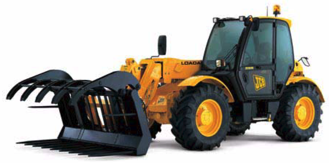
Service Manual
Side Engine Loadalls
Section 1 – General Information
Section 2 – Care and Safety
Section 3 – Routine Maintenance
Section B – Body and Framework
Section C – Electrics
Section E – Hydraulics
Section F – Transmission
Section G – Brakes
Section H – Steering
Section K – Engine
Section M – Electronic Data Systems
…
Main System Pressures
To investigate any hydraulic performance issues you must complete the pressure tests.
– Stand-by Pressure – This is the pressure measured at the pump when the hydraulic services are not operated.
– Delta P Pressure – This is the pressure setting of the pump controller. The controller makes sure that the pump delivers a pressure above what is required by
the hydraulic services. This extra pressure is the delta P pressure.
– Load Sense Relief Valve Pressure – This is the maximum pressure that can be achieved within the hydraulic system.
Note: This procedure describes the correct method to check the main system pressure, load sense pressure, pump standby pressure, steering pressure and delta-P
pressure. A multi-channel digital pressure test set will be required to measure the pressures accurately (see Service Tools).
…