INSTANT DOWNLOAD (add to cart)
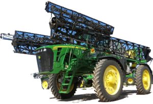
Complete technical manual (Repair) with electrical wiring diagrams for John Deere 4860 Self-Propelled Sprayer. It’s the same service manual used by dealers that guaranteed to be fully functional and intact without any missing page.
This John Deere 4860 Self-Propelled Sprayer Repair Manual (TM1386) is divided into different sections. Each section covers a specific component or system with detailed illustrations. A table of contents is placed at the beginning of each section. Pages are easily found by category, and each page is expandable for great detail. The printer-ready PDF documents work like a charm on all kinds of devices.
TM1386 – John Deere 4860 Self-Propelled Sprayer Repair Manual
2,521 pages, bookmarked, Searchable, Printable, high quality PDF
Table of Contents
Foreword
10 – General Information
20 – Engine
30 – Fuel and Air System
40 – Electrical System
50 – Power Train
60 – Steering and Brakes
61 – Steering and Tread Adjust Repair
70 – Hydraulic System
80 – Solution Spray System
81 – Foam Marker System
82 – Dry Box Conversion
90 – Operator Station
100 – Boom Repair
199- Dealer Fabricated Tools
…
EXCERPT:
2. Remove socket head cap screws (P) and end cover (Q).
3. Replace O-rings (O and H).
4. Remove socket head cap screws (G) and control valve (F).
CAUTION: Control valve (F) is under spring pressure. Secure control valve while removing socket head cap screws (G)
5. Replace O-rings (E and H).
6. Remove cap (C).
7. Measure and record distance (R). Measurement is taken from end of adjusting screw (B and D) and lock nut seal, as shown.
IMPORTANT: Measure and record distance (R) before removing adjusting screws (B and D). Measurement is needed for reassembly.
8. Remove adjustment screw (B).
9. Remove and replace adjustment screw (B) with adjustment screw (D) from location (I). Adjust screw inward to swivel rotary group to zero position as shown.
…

