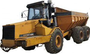
Pages from SEBMHA250104 – Articulated Dump Truck HA250-1, HA250-3, HA270-1, HA270-3 Shop Manual
Complete workshop & service manual with electrical wiring diagrams for Komatsu Articulated Dump Truck HA250-1, HA250-3, HA270-1, HA270-3. It’s the same service manual used by dealers that guaranteed to be fully functional and intact without any missing page.
This Komatsu Articulated Dump Truck HA250-1, HA250-3, HA270-1, HA270-3 service & repair manual (including maintenance, overhaul, disassembling & assembling, adjustment, tune-up, operation, inspecting, diagnostic & troubleshooting…) is divided into different sections. Each section covers a specific component or system with detailed illustrations. A table of contents is placed at the beginning of each section. Pages are easily found by category, and each page is expandable for great detail. The printer-ready PDF documents work like a charm on all kinds of devices.
SEBMHA250104 – Articulated Dump Truck HA250-1 & HA270-1 Shop Manual.pdf
SEBMHA250104 – Articulated Dump Truck HA250-1, HA250-3, HA270-1, HA270-3 Shop Manual.pdf
XEAMM00100 – Articulated Dump Truck HA250-3, HA270-3 Operation & Maintenance Manual.pdf
EXCERPT:
GOVERNOR
The governor controls pressure level in the wet reservoir of the brake system. The governor controls the relief mechanism of the compressor so that it stops charging when max. working pressure has been reached and starts charging when the pressure has dropped below minimum working pressure.
Compressor charging
Compressed air flows through the pipe from the wet reservoir through inlet 1 to the space above piston 5. When air pressure increases the piston is pressed down and compresses spring 8. Pressure rod 7 and vent pipe 6 cannot move down.
Compressor relieved
When piston 5 is pressed down, vent pipe 6 prevents valve disc 4 from following. Air passes past the valve disc out through the hole in the piston and on through outlet 2 to the compressor relief mechanism which opens intake valves whereby compression is interrupted.
Relief, final phase
The cylinder diameter at the lower 0 ring is larger than that at upper. Air now presses on top of the piston as well as the surface at the lower O ring.
Pressure required to retain the piston therefore becomes less than that which originally pressed down the piston.
…
