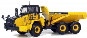
Pages from SEN04733-02 – Articulated Dump Truck HM250-2 Shop Manual
Complete workshop & service manual with electrical wiring diagrams for Komatsu Articulated Dump Truck HM250-2. It’s the same service manual used by dealers that guaranteed to be fully functional and intact without any missing page.
This Komatsu Articulated Dump Truck HM250-2 service & repair manual (including maintenance, overhaul, disassembling & assembling, adjustment, tune-up, operation, inspecting, diagnostic & troubleshooting…) is divided into different sections. Each section covers a specific component or system with detailed illustrations. A table of contents is placed at the beginning of each section. Pages are easily found by category, and each page is expandable for great detail. The printer-ready PDF documents work like a charm on all kinds of devices.
FILELIST:
EEAM027602 – Articulated Dump Truck HM250-2 Operation & Maintenance Manual.pdf
EPAM027602 – Camião Basculante Articulado HM350-2 Manual de Operação e Manutenção.pdf
GEN00094-00 – Articulated Dump Truck HM250-2 Field Assembly Manual.pdf
PEN00334-01 – Articulated Dump Truck HM250-2 Operation & Maintenance Manual.pdf
PEN00371-01 – Articulated Dump Truck HM250-2 Operation & Maintenance Manual.pdf
PEN00472-07 – Articulated Dump Truck HM250-2 Operation & Maintenance Manual.pdf
SEN04733-02 – Articulated Dump Truck HM250-2 Shop Manual.pdf
SEN04733-07 – Articulated Dump Truck HM250-2 Shop Manual.pdf
TEN00321-01 – Articulated Dump Truck HM250-2 Operation & Maintenance Manual.pdf
TEN00343-01 – Articulated Dump Truck HM250-2 Operation & Maintenance Manual.pdf
TEN00441-07 – Articulated Dump Truck HM250-2 Operation & Maintenance Manual.pdf
EXCERPT:
500 Hydraulic system
Removal and installation of hoist valve assembly
Removal and installation of hoist valve assembly
Removal
Disconnect the cable from the negative (ñ) terminal of the battery.
Check that the body is lowered completely.
Loosen the hydraulic oil filler cap to release the internal pressure of the hydraulic tank.
1. Drain hydraulic oil. Hydraulic tank: 120l
2. Remove left fender – inner cover assembly (1). Left fender – inner cover assembly: 85 kg
3. Tilt up the cab. For detail, see “How to tilt up cab”.
4. Remove the following to slide the bracket (12) of EPC valve (2).
5. Remove bracket (12). Disconnect clamp of the hose (H) on the back of the bracket.
6. Disconnect the following piping from the hoist valve (13).
Disconnect the tube coupling.
Do not separate the tube assembly (15) because of the orifice in A portion.
…
