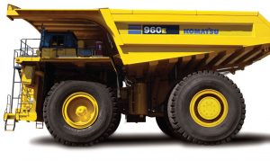
Complete digital official shop manual contains service, maintenance, and troubleshooting information for the Komatsu Dump Truck 960E-1, 960E-2, 960E-2K, 960E-2KT. Diagnostic and repair procedures are covered in great detail to repair, maintain, rebuild, refurbish or restore your trucks like a professional mechanic in local service/repair workshop. This cost-effective quality manual is 100% complete and intact as should be without any missing pages. It is the same factory shop manual used by dealers that guaranteed to be fully functional to save your precious time.
This manual for Komatsu Komatsu Dump Truck 960E-1, 960E-2, 960E-2K, 960E-2KT is divided into different sections. Each section covers a specific component or system and, in addition to the standard service procedures, includes disassembling, inspecting, and assembling instructions. A table of contents is placed at the beginning of each section. Pages are easily found by category, and each page is expandable for great detail. It is in the cross-platform PDF document format so that it works like a charm on all kinds of devices. You do not need to be skilled with a computer to use the manual.
CEAM022100 – Dump Truck 960E-1K Operation & Maintenance Manual.pdf
CEAM022901 – Dump Truck 960E-1 Operation & Maintenance Manual.pdf
CEAM026101 – Dump Truck 960E-2 Operation & Maintenance Manual.pdf
CEAM026401 – Dump Truck 960E-2K Operation & Maintenance Manual.pdf
CEAW005502 – Dump Truck 960E-1 Field Assembly Manual.pdf
CEAW005503 – Dump Truck 960E-1 Field Assembly Manual.pdf
CEAW006500 – Dump Truck 960E-1K Field Assembly Manual.pdf
CEAW006502 – Dump Truck 960E-2K Field Assembly Manual.pdf
CEAW007302 – Dump Truck 960E-2 Field Assembly Manual.pdf
CEBM021300 – Dump Truck 960E-1 Shop Manual.pdf
CEBM021304 – Dump Truck 960E-1 Shop Manual.pdf
CEBM022602 – Dump Truck 960E-1 Shop Manual.pdf
CEBM023802 – Dump Truck 960E-1 Shop Manual.pdf
CEBM025901 – Dump Truck 960E-2 Shop Manual.pdf
CEBM026301 – Dump Truck 960E-2K Shop Manual.pdf
CEBM028400 – Dump Truck 960E-2KT Shop Manual.pdf
EXCERPT:
50 Disassembly and assembly
Removal and installation of rear axle
Removal
1. Park the truck on firm, level ground and chock the rear wheels to prevent truck movement.
2. Shut down the truck. For the proper shutdown procedure, refer to Index and foreword section Operating instructions.
3. Remove the dump body. Refer to Disassembly and assembly section Body and structures.
4. Block up the truck and remove the rear wheels.
Refer to “Removal and installation of rear wheel”.
5. Loosen the hose clamps and disconnect axle air blower hose (1, Figure 50-17) from wheel motor cooling air duct (2).
6. Install vacuum pump kit (XB0887) on the hydraulic tank to prevent the loss of oil when disconnecting hydraulic lines.
7. Remove the drain plugs at the bottom of the rear brake assemblies. Allow the oil to drain from the brakes into a suitable container.
FIGURE 50-17. REAR AXLE HOUSING
1. Axle Air Blower Hose
2. Wheel Motor Cooling Air Duct
3. Power Cable Mount
4. Hydraulic Hose Manifold
8. Disconnect and unclamp the hoses at hydraulic hose manifold (4) on the left side of the rear axle housing. Cap the fittings and plug the hoses to prevent contamination.
9. Remove the power cable grips at power cable mount (3) on the right side of the rear axle housing. Slide the cable grips forward on the cables.
10. Disconnect the brake cooling lines at each brake assembly back plate. Disconnect the brake apply lines. Cap and plug all openings.
11. After all hydraulic lines have been reconnected, turn off the vacuum pump and remove the vacuum pump from the hydraulic tank.
12. Remove the clamps that secure the brake hoses to the spindles.
NOTE: For access to components inside the rear axle housing, the rear hatch can be opened and the top cover can be removed.
13. Disconnect and cap the parking brake supply lines to the parking brake on each wheel motor.
14. Remove the wheel motor cooling air duct from between the wheel motors.
15. Disconnect all wheel motor power cables and electrical harnesses at their terminals. Remove the cable clamps and pull the cables and harnesses from the rear axle housing.
16. Disconnect and unclamp any electrical harnesses that are attached to the rear axle housing as necessary.
17. Remove all automatic lubrication system hoses and clamps that are attached to the rear axle housing. Secure the hoses to the frame to prevent interference during rear axle housing removal.
18. Remove the wheel motors. Refer to “Removal and installation of wheel motor”.
19. Remove the rear suspensions. Refer to
Disassembly and assembly section
Suspensions.
20. Remove the anti-sway bar. Refer to “Removal and installation of anti-sway bar”.
21. Remove the pivot pin. Refer to “Removal and installation of pivot pin”.
22. Attach an overhead hoist or crane to the lifting eyes on the rear axle housing and move it away from the rear of the frame.
…
