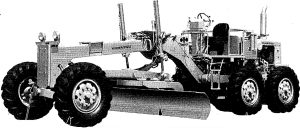
Pages from SEBMG5250107 – Motor Grader GD510 & GD520 Series Shop Manual
Complete workshop & service manual with electrical wiring diagrams for Komatsu Motor Grader GD500R-2, GD505R-2, GD505A-2, GD521A-1, GD522A-1, GD523A-1, GD525A-1, GD511A-1, GD513A-1, GD521R-1, GD523R-1, GD511R-1, GD513R-1, GD510R-1, GD515A-1, GD525A-1C, GD525A-1A, GD525A-1B. It’s the same service manual used by dealers that guaranteed to be fully functional and intact without any missing page.
This Komatsu Motor Grader GD500R-2, GD505R-2, GD505A-2, GD521A-1, GD522A-1, GD523A-1, GD525A-1, GD511A-1, GD513A-1, GD521R-1, GD523R-1, GD511R-1, GD513R-1, GD510R-1, GD515A-1, GD525A-1C, GD525A-1A, GD525A-1B service & repair manual (including maintenance, overhaul, disassembling & assembling, adjustment, tune-up, operation, inspecting, diagnostic & troubleshooting…) is divided into different sections. Each section covers a specific component or system with detailed illustrations. A table of contents is placed at the beginning of each section. Pages are easily found by category, and each page is expandable for great detail. The printer-ready PDF documents work like a charm on all kinds of devices.
SEAM23AB01 – Motor Grader GD500R-2 Series Operation & Maintenance Manual.pdf
SEAM236A01 – Motor Grader GD200A-1 Series Operation & Maintenance Manual.pdf
SEAMG5110103 – Motor Grader GD511A-1, GD521A-1, GD523A-1 Series Operation & Maintenance Manual.pdf
SEAMG5110104 – Motor Grader GD511A-1, GD521A-1, GD523A-1 Series Operation & Maintenance Manual.pdf
SEBM023AB07 – Motor Grader GD500-2 (GD500R-2, GD505R-2, GD505A-2) Series Shop Manual.pdf
SEBMG5250107 – Motor Grader GD510 & GD520 Series Shop Manual.pdf
EXCERPT:
OPERATION
1. Brake applied
When the brake pedal is depressed, the air circuit is connected to chamber A of the disc brake. When the air pressure is greater than the pushing force of spring (7), piston (9) moves to the left, and pushes discs (4) and plates (5). Friction is generated between the discs (meshed with gear (2)) and the plates (meshed with cage (1 0)). This slows down the rotation of the discs and finally stops it. In other words, the brake is applied.
2. Brake released
When the brake pedal is released, the air m chamber A is released. Spring (7) moves piston (9) back to the right, so the pushing force is reduced. This removes the friction between discs (4) and plates (5), and allows them to rotate freely. In other words, the brake is released.
…
