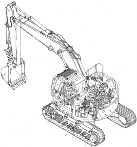
Pages from 604.13.436 – E235SR Workshop Manual
Complete workshop & service manual with electrical wiring diagrams for New Holland/Kobelco E200SR/E225BSR/E235SR/E235BSR Excavators. It’s the same service manual used by dealers that guaranteed to be fully functional and intact without any missing page.
This New Holland/Kobelco E200SR/E225BSR/E235SR/E235BSR Excavators service & repair manual (including maintenance, overhaul, disassembling & assembling, adjustment, tune-up, operation, inspecting, diagnostic & troubleshooting…) is divided into different sections. Each section covers a specific component or system with detailed illustrations. A table of contents is placed at the beginning of each section. Pages are easily found by category, and each page is expandable for great detail. The printer-ready PDF documents work like a charm on all kinds of devices.
FILELIST:
604.13.431 – E200SR Excavators Workshop Manual.pdf
604.13.436 – E235SR Workshop Manual.pdf
87677758A – New Holland_Kobelco E235BSR Workshop Manual.pdf
87709239A – New Holland_Kobelco E225BSR Workshop Manual.pdf
EXCERPT:
INDEX
SPECIFICATIONS
Section 1 – Outline
Section 2 – Specification
Section 3 – Attachment dimension
MAINTENANCE
Section 11 – Tools
Section 12 – Standard maintenance time schedule
Section 13 – Maintenance standard and test procedure
SYSTEM
Section 21 – Mechatro control system
Section 22 – Hydraulic system
Section 23 – Electric system
Section 24 – Components system
Section 25 – Air-conditioner system
DISASSEMBLING
Section 31 – Disassembling and assembling
Section 32 – Attachment
Section 33 – Upper structure
Section 34 – Travel system
TROUBLESHOOTING
Section 41 – Troubleshooting (mechatro control)
Section 42 – Troubleshooting (Hydraulic)
Section 43 – Troubleshooting (Electric)
Section 44 – Troubleshooting (Engine)
ENGINE
Section 51 – Engine
OPT
Section 63 – Mounting the breaker and nibbler & breaker
…
This section describes the following operations.
1) Pressure drain (releasing) pilot circuit
2) Pressure drain (releasing) main circuit
11.1 PRESSURE RELEASE PILOT CIRCUIT
Purpose :
To release the main circuit pressure for piping repair work.
Mechatronics :
When press screen change switch of gauge cluster and buzzer stop switch at the same time for more than 5 seconds, mechatro controller recognizes this is pressure release control and out puts the following command.
1) Puts out the minimum tilting command value to the pump proportional valve (PSV-P1, PSV-P2).
2) Puts out a pressure release control revolution command value to the governor motor. (Electric system).
3) Travel straight solenoid proportional valve (PSV-C) is input the command value to change the pressure release position.
4) Puts out a standby command value to the P1, P2 bypass cut proportional valves. (A command that does not put out the secondary pressure of the P1, P2 bypass proportional valves).
Hydraulics :
1) The pump proportional valve minimizes the delivery rates of the P1, P2 pumps.
2) The secondary pilot pressure for the travel straight valve pressure release position selection comes out of the travel straight proportional valve (PSV-C), flows into the PTb port of C/V (2) and switches the travel straight valve to its pressure release position.
11.2 PRESSURE RELEASE MAIN CIRCUIT
Operation:
When the operating lever is shifted to neutral during engine running, if the pressure is drained (released) as mentioned left, “DRAINING HYD. PRESS” is displayed on the gauge cluster and intermittent buzzer sound continuously. If the operating lever for the circuit required releasing pressure is operated four to five times, pressure draining may be completed. After draining pressure is completed, turn off the starter key, and buzzer stops. If the pump pressure is determined to be more than 9.8kgf/cm2 (140 psi) by the output value of the high-pressure sensor or the high-pressure sensors (SE-22, 23) are broken, “FAIL DRAIN HYD. PRESS” is displayed on the gauge cluster and the buzzer sounds continuously. In that case, also the buzzer is not stopped unless the engine key is turned to off. Repeat the pressure releasing procedure once again.
Operation:
If the travel straight valve is turned to the pressure release position, the oil delivered by each pump is unloaded to the tank passage. If the spools are switched by pilot operation, the remaining pressure from the actuators may be relieved to the tank circuit, i.e. the main circuit pressure may be released.
11. PRESSURE DRAINING (RELEASING) CIRCUIT