INSTANT DOWNLOAD (add to cart)

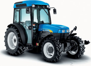
Complete workshop & service manual with electrical wiring diagrams for New Holland TN75FA, TN85FA, TN95FA Tractors. It’s the same service manual used by dealers that guaranteed to be fully functional and intact without any missing page.
This New Holland TN75FA, TN85FA, TN95FA Tractors service & repair manual (including maintenance, overhaul, disassembling & assembling, adjustment, tune-up, operation, inspecting, diagnostic & troubleshooting…) is divided into different sections. Each section covers a specific component or system with detailed illustrations. A table of contents is placed at the beginning of each section. Pages are easily found by category, and each page is expandable for great detail. The printer-ready PDF documents work like a charm on all kinds of devices.
1,460 + 204 + 192 pages, bookmarked, Searchable, Printable, high quality PDF
FILELIST:
87675643 – TN75FA, TN85FA, TN95FA Tractors Service Manual.pdf
87034097 – TN55, TN65, TN70, TN75 Repair Manual (Section 55 – Electrical System, Section 90 – Platform, Cab, Bodywork).pdf
87393901 – TN60A, TN70A, TN75A, TN85A, TN95A Repair Manual (Section 55 – Electrical System, Section 90 – Platform, Cab, Bodywork).pdf
The following pages are the collation of the contents pages from each section and chapter of the TNFA Series Repair manual. Complete Repair part # 87675643.
The sections used through out all New Holland product Repair manuals may not be used for each product. Each Repair manual will be made up of one or several books. Each book will be labeled as to which sections are in the overall Repair manual and which sections are in each book.
The sections listed above are the sections utilized for the TNFA Series Tractors.
…
EXCERPT:
SECTION 41 – STEERING – CHAPTER 1
DESCRIPTION AND OPERATION
Neutral position
When the steering wheel (V, fig. 3) is not moving, the rotating valve (3) is located in the neutral position in relation to the sleeve (4). In this position, retained by springs (2), the following occurs:
– the pin (1) will be in the central position in relation to the holes on the rotating valve (3);
– the ducts (5 and 6) are aligned (sect. C-C) and the oil, from the pump (P, fig. 3), flows freely to and from the reservoir;
– the grooves (7, 9 and 11) on valve (sect. D-D, E-E) are not aligned with the ducts (8, 10 and 12) on the sleeve, therefore all connecting lines with the steer- ing cylinder(s) remain closed.
Right-hand steering control
By turning the steering wheel (V, fig. 3) clockwise, the springs (2) allow the rotating valve (3) to rotate in relation to the sleeve (4), until the clearance G1 is re- covered (sect. B-B).
Under these conditions the following occurs:
– the ducts (9 and 6) are not aligned, therefore the oil discharge flow is interrupted;
– the six grooves (7) are aligned with the same number of ducts (8), that are connected with the compartments on the rotor in the suction phase;
– the six delivery grooves are aligned with the ducts (10) connected to the steering cylinder and, at the same time, the grooves are aligned with the remaining ducts (8, sect. D-D), that are connected with the compartments on the rotor in the delivery phase;
– the six discharge grooves (11) align with the ducts (12) connecting to the cylinder.
Once the clearance (G1) has been recovered, the valve (3) rigidly transmits the steering wheel rotation to the sleeve (4) and rotor, by means of the pin and shaft (1).
The details (d, e, fig. 2), illustrate how the mechanism operates at the start of a turn to the right and after a certain number of steering wheel rotations.
Note that there is an uninterrupted connection be- tween the oil from the pump with the compartments on the rotor in the suction phase (and with oil when the compartments on the rotor are in the delivery phase) and the relative duct connected to the steering cylinder.
…
