Posted on

Case 1150M Tier 4A (interim) Crawler Dozer Service Manual Factory Service & Shop Manual


Download Link

INSTANT DOWNLOAD (add to cart)


Case 1150M Tier 4A (interim) Crawler Dozer Service Manual Factory Service & Shop Manual

2,200+ total pages, bookmarked, Searchable, Printable, high quality PDF

51418567 (Nov.2017, replace 47907865) – Case 1150M Tier 4A (interim) Crawler Dozer Service Manual.pdf – 2,281 pages
PIN NCDC11500 and above; PIN NDDC11000 and above; PIN NEDC11000 and above; PIN NFDC11000 and above; PIN NFC105000 and above
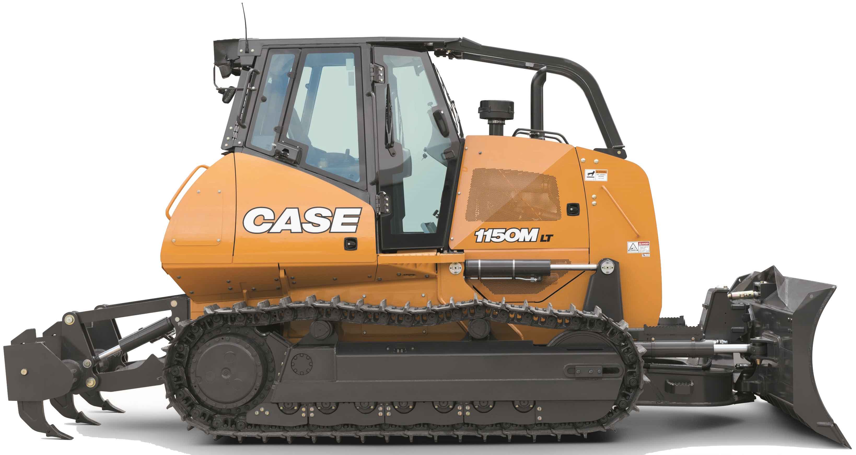
1150M Long Track (LT) – Tier 4A (interim) and Stage IIIB [NFC105000 – ], 1150M Long Track (LT) [NCDC11500 – ], 1150M Long Track (LT) [NDDC11000 – ], 1150M Long Track (LT) [NEDC11000 – ], 1150M Long Track (LT) [NFDC11000 – ], 1150M Wide Track (WT) / Low Ground Pressure (LGP) [NCDC11500 – ], 1150M Wide Track (WT) / Low Ground Pressure (LGP) [NDDC11000 – ], 1150M Wide Track (WT) / Low Ground Pressure (LGP) [NEDC11000 – ], 1150M Wide Track (WT) / Low Ground Pressure (LGP) [NFDC11000 – ], 1150M Wide Track (WT) / Low Ground Pressure (LGP) – Tier 4A (interim) and Stage IIIB [NFC105000 – ]

47907890 (replaces 47619956) – Electrical Schematic 1150M:1650M TIER 4A (Interim):STAGE IIIB.pdf

Complete workshop & service manual with electrical wiring diagrams for Case 1150M Tier 4A (interim) Crawler Dozer. It’s the same service manual used by dealers that guaranteed to be fully functional and intact without any missing page.

This Case 1150M Tier 4A (interim) Crawler Dozer service & repair manual (including maintenance, overhaul, disassembling & assembling, adjustment, tune-up, operation, inspecting, diagnostic & troubleshooting…) is divided into different sections. Each section covers a specific component or system with detailed illustrations. A table of contents is placed at the beginning of each section. Pages are easily found by category, and each page is expandable for great detail. The printer-ready PDF documents work like a charm on all kinds of devices.

EXCERPT:
Contents
INTRODUCTION
Engine… 10
[10.001] Engine and crankcase … 10.1
[10.202] Air cleaners and lines … 10.2
[10.206] Fuel filters … 10.3
[10.216] Fuel tanks … 10.4
[10.304] Engine lubrication system … 10.5
[10.310] Aftercooler… 10.6
[10.400] Engine cooling system … 10.7
[10.414] Fan and drive … 10.8
[10.500] Selective Catalytic Reduction (SCR) exhaust treatment … 10.9
Hydrostatic drive.. 29
[29.218] Pump and motor components… 29.1
Brakes and controls … 33
[33.110] Parking brake or parking lock … 33.1
[33.202] Hydraulic service brakes … 33.2
Hydraulic systems… 35
[35.000] Hydraulic systems… 35.1
[35.300] Reservoir, cooler, and filters… 35.2
[35.104] Fixed displacement pump … 35.3
[35.105] Charge pump… 35.4
[35.359] Main control valve … 35.5
[35.741] Dozer blade cylinders … 35.6
Tracks and track suspension … 48
[48.130] Track frame and driving wheels … 48.1
[48.100] Tracks … 48.2
[48.134] Track tension units … 48.3
[48.138] Track rollers … 48.4
[48.140] Dropbox and final drive … 48.5
[48.AAA] Tracks and track suspension generic sub-group … 48.6
Cab climate control … 50
[50.100] Heating … 50.1
[50.104] Ventilation … 50.2
[50.200] Air conditioning… 50.3
Electrical systems … 55
[55.000] Electrical system … 55.1
[55.011] Fuel tank system … 55.2
[55.014] Engine intake and exhaust system… 55.3
[55.015] Engine control system… 55.4
[55.030] Service brake electrical system … 55.5
[55.050] Heating, Ventilation, and Air-Conditioning (HVAC) control system… 55.6
[55.100] Harnesses and connectors… 55.7
[55.201] Engine starting system … 55.8
[55.202] Cold start aid … 55.9
[55.301] Alternator… 55.10
[55.302] Battery… 55.11
[55.408] Warning indicators, alarms, and instruments … 55.12
[55.512] Cab controls… 55.13
[55.518] Wiper and washer system… 55.14
[55.988] Selective Catalytic Reduction (SCR) electrical system … 55.15
[55.DTC] FAULT CODES… 55.16
Dozer blade and arm.. 86
[86.110] Dozer blade … 86.1
[86.124] Dozer pushbeams and struts … 86.2
Platform, cab, bodywork, and decals … 90
[90.150] Cab… 90.1
[90.160] Cab interior trim and panels… 90.2
[90.120] Mechanically-adjusted operator seat… 90.3
[90.124] Pneumatically-adjusted operator seat… 90.4
[90.100] Engine hood and panels … 90.5

Posted on

Case 1150E, 1155E Crawler Workshop Repair & Service Manual + Operator’s Manual


Download Link

INSTANT DOWNLOAD (add to cart)


1,500+ total pages, bookmarked, Searchable, Printable, high quality PDF

“Service Manual.pdf”
Case 1150E, 1155E Crawler Service Manual
1,503 pages

“9-9942.pdf”
Case 1150E, 1155E Crawler Operator’s Manual
158 pages

Complete digital official shop manual contains service, maintenance, and troubleshooting information for the Case 1150E, 1155E Crawler. Diagnostic and repair procedures are covered in great detail to repair, maintain, rebuild, refurbish or restore your Case 1150E, 1155E Crawler like a professional mechanic in local service/repair workshop. This cost-effective quality manual is 100% complete and intact as should be without any missing pages. It is the same factory shop manual used by dealers that guaranteed to be fully functional to save your precious time.

This manual for Case 1150E, 1155E Crawler is divided into different sections. Each section covers a specific component or system and, in addition to the standard service procedures, includes disassembling, inspecting, and assembling instructions. A table of contents is placed at the beginning of each section. Pages are easily found by category, and each page is expandable for great detail. It is in the cross-platform PDF document format so that it works like a charm on all kinds of devices. You do not need to be skilled with a computer to use the manual.

EXCERPT:

CAUSES OF PREMATURE TURBOCHARGER FAILURE
Certain operating and maintenance conditions can arise which could cause premature turbocharger failure. NOTE: The total solution to the problem is not in repairing the failure, but in determining the cause. Replacing a damaged turbocharger without determining the cause will frequently result in a repeat failure.
Lack of Lubricating Oil
This type of failure can occur when the amount of oil being supplied to the turbocharger is insufficient to lubricate or cool bearing and journal surfaces.
Operating temperatures affect the volume of oil required by the turbocharger. As turbocharger speed or engine load increases, the need for lubricating oil increases. NOTE: Insufficient oil for periods as short as five seconds can cause failure. This is why it is necessary to prime the turbocharger as part of the everyday operating procedure. IMPORTANT:
It is very important that adequate lubrication reaches the turbocharger bearings and throughout the engine before operating the engine at rated speed.
Priming The Turbocharger
1. Place the transmission range shift lever in “N” Neutral position.
2. Set the throttle lever not more than 1/3 open position (1000 RPM).
3. Push in the fuel shutoff control. Press starter button until engine starts. IMPORTANT: Do not increase throttle or apply load until normal oil pressure shows on the engine oil pressure gauge, assuring proper lubrication to the turbocharger.
IMPORTANT: In very cold weather, at oil filter change or when the tractor has been idle for several weeks or more, proceed as follows to prime the turbocharger.
Pull out the fuel shutoff control, press the start button and hold. Allow the engine to crank until the engine oil pressure gauge pointer reaches the green zone. Do not exceed 30 seconds cranking time.
Push in the fuel shutoff control and press the start button. Run the engine (about 2 min.
max.) at 1000 RPM until normal engine oil pressure shows on the engine oil pressure gauge assuring proper lubrication to the turbocharger.
4. If the engine fires and stops, wait for the starting motor to stop spinning before attempting another start.
5. Do not use the starting motor longer than 30 seconds without interruption. Wait at least 3 minutes between crankings so batteries can recuperate and the starting motor can cool.
6. Should the engine kill when operating under load, immediately restart the engine to prevent over-heating caused by stopping the flow of oil for turbocharger, cooling and lubrication.
Foreign Material or Dirt in the Lubricating System.
Operating the engine with contaminated oil will cause damage to the turbocharger bearings if the particles are of sufficient quantity.
If the particles are large enough, they can clog the internal oil passages and starve the bearings. This is another reason why it is important to change the engine crankcase oil and oil filters at regular specified intervals.
Foreign Material in Exhaust or Air Intake Systems.
The rotating parts of the turbocharger can be damaged by particles introduced through the air intake, which makes proper maintenance of the air cleaner system very important.
High Exhaust Temperature
Excessive temperature in the exhaust system will cause lubricating oil to coke in the center housing drain annulus at the turbine end. Oil leakage, carbon deposits and eventual damage to the back of the turbine wheel will result.
High exhaust temperature can also erode the turbine housing creating pitting and deposits on the turbine wheel.
High exhaust temperature can be caused by the turbocharger itself. Carbon build up on the turbine wheel, if severe, will slow the rotating assembly, reducing the amount of inlet air.

Posted on

Case 1150B Crawler Workshop Repair & Service Manual


Download Link

INSTANT DOWNLOAD (add to cart)


Case 1150B Crawler Workshop Repair & Service Manual

900+ total pages, bookmarked, Searchable, Printable, high quality PDF

“9-72547.pdf”
Case 1150B Crawler Service Manual
867 pages

“9-4267.pdf”
Case 1150B Crawler Operator’s Manual
122 pages

Complete digital official shop manual contains service, maintenance, and troubleshooting information for the Case 1150B Crawler. Diagnostic and repair procedures are covered in great detail to repair, maintain, rebuild, refurbish or restore your Case 1150B Crawler like a professional mechanic in local service/repair workshop. This cost-effective quality manual is 100% complete and intact as should be without any missing pages. It is the same factory shop manual used by dealers that guaranteed to be fully functional to save your precious time.

This manual for Case 1150B Crawler is divided into different sections. Each section covers a specific component or system and, in addition to the standard service procedures, includes disassembling, inspecting, and assembling instructions. A table of contents is placed at the beginning of each section. Pages are easily found by category, and each page is expandable for great detail. It is in the cross-platform PDF document format so that it works like a charm on all kinds of devices. You do not need to be skilled with a computer to use the manual.

EXCERPT:
MODEL 11508 CRAWLER
TABLE OF CONTENTS
10 SERIES- GENERAL
General Engine Specifications … 1010
Detailed Engine Specifications … 1021
Detailed Fuel Specifications .. 1030
Maintenance and Lubrication .. 1050
Torque Chart … 1051
20 SERIES- ENGINE
Engine Diagnosis … 2001
Engine Tune-Up .. 2002
Cylinder Head, Valve Train and Camshaft … 2015
Cylinder Block, Sleeves, Pistons and Rods .. 2025
Crankshaft, Main Bearing, Flywheel and Oil Seal Replacement … 2035
Lubrication System .. 2046
Stall Checks, Engine Removal and Installation .. 2050
Air Cleaner … 2051
Ether Injector Starting Aid … 2053
Cooling System … 2055
30 SERIES – FUEL SYSTEM
Fuel System and Filter … 301 0
Fuel Injection Pumps … 3012
Fuel Injectors … 3013
Fuel Tank, Lines and Throttle Adjustment … 3052
40 SERIES- HYDRAULICS
Diagrams, Troubleshooting, Maintenance, Adjustments .. 4011
Flowmeter Tests … 4011 A
Exploded Views of Hydraulic System … 4012
Diversion Valve R24819 .. 4012A
Equipment Pump R25852 … .4013
Equipment Control Valves … 4016
Loader, Ripper and Dozer Cylinders .. 4057
50 SERIES- TRACK AND SUSPENSION
Track System … 5010
Track System- Idlers (Without Lubricant Fill Plug in Hub) .. 5010A
Track System- Track Frame Removal and Installation .. 5010B
Suspension System … 5019
Guide Levers .. 5019A
Intertrac Rollers … 5505
60 SERIES- POWER TRAIN
Transmission Oil Flow- Diagrams and Operations … 6011
Troubleshooting -Transmission/Torque Converter and
Hydraulic System … 6012
Diagram, Service, Transmission Removal, Controls .. 6013
Transmission Control Valve .. 6015
Torque Converter … 6016
Charging Pump R25586 .. 6017
Drive Shafts … 6022
Crawler Transmission … 6025
Transmission, Final Drives … 6026
Transmission Brakes .. 6027
70 SERIES – BRAKES
Brakes – See Section 6027
Brake Pedals and Linkage, Parking Brake … 7010
80 SERIES- ELECTRICAL
Wiring Diagram … 8011
Troubleshooting .. 8012
Battery … 8014
Starter and Starter Solenoid .. 8015
Alternator … 8016
90. SERIES- MOUNTED EQUIPMENT
Loader … 9011
Power Tilt Dozer, Power Angle-Tilt-Pitch (ATP) Dozer … 9013
Field Removal/Installation of ATP Dozer
Blade for Transport- Supplement 1 … 9013
W5A Hyster Winch .. 9014
Ripper … 9015
ROPS .. 9019

Disassembly
1. Remove the pipe plug from the hub and drain the oil. This pipe plug is coated with Loctite Pipe Sealant and may be difficult to break loose. If required, a small amount of heat may be applied to the plug.
2. Remove the shaft lock nut from either end of the shaft. These nuts are factory torqued to 210-230 foot-pounds.
3. Remove the washer and seal retainer from the shaft. The seal retainer is held on the shaft only by the fit of an internal 0-ring, Figure 48.
4. Remove the remaining half of the face seal assembly from the !’Oller if it did not come out with the seal retainer.
5. Place the roller in a press and press the shaft and the parts still assembled to it from the roller hub. Use a sleeve or combination of sleeves of the proper length and diameter to prevent damage to the shaft or roller hub, Figure 49.
NOTE: Before pressing shaft from roller hub, place container under roller. As shaft is pressed out, any oil remaining inside reservoir of hub will run out.
6. Use a puller to remove the bearing cone and seal spacer from the side of the hub from which shaft was pressed. The seal spacer on the opposite side of the hub will be removed when the shaft is pressed from the roller, step 5.
7. Disassemble parts remaining on the shaft:
a. Clamp the shaft in a vise between brass or wood strips and remove the shaft lock nut.
b. Remove the washer and seal retainer.
c. Remove the face seal assembly from the seal retainer.
d. Press the bearing cone from the shaft.
8. Remove the Q-ring from the bore of the seal retainers.
9. A bearing cup is pressed into each side of the hub. Do not remove these cups unless they are to be replaced. To remove:
a. Fabricate the special tool shown in Figure 6.
b. Place the roller under a press. Insert the tool into the hub as shown in Figure 50 and press out the cup.
Inspection
1. Thoroughly wash all parts before inspection.
2. Clean the roller. The internal cavities of the roller must be free from the dirt, chips, rust, and all other foreign matter.
3. Make a visual inspection of the shaft and – bearings. If the bearing cones or bearing cups show excessive wear or if they are pitted, they should be replaced.
4. Disassemble the face seal assemblies.
Inspect the metal sealing rings carefully.
The area of contact between the two rings must not be in the inner half of the faces and the rings must be wearing evenly.
If the sealing rings must be replaced, replace the entire face seal assembly.
5. Discard the rubber seals even if they appear to be in good condition. A kit is available for replacement of the seals only; refer to the Case Parts Catalog.
6. Install new 0-rings in the seal retainers.
Assembly
Refer to Figures 47 and 48.
Figure 49 – Removing the Shaft
BEARING CUP
Figure 50- Bearing Cup Removal

Posted on

Case 1150 Crawler Workshop Repair & Service Manual + Operator’s Manual


Download Link

INSTANT DOWNLOAD (add to cart)


total 1,000+ pages, bookmarked, Searchable, Printable, high quality PDF

“9-72483.pdf”
Case 1150 Crawler Service Manual
942 pages

“9-1733.pdf”
Case 1150 Crawler Operator’s Manual (S/N 7106801-7108998)
208 pages

“9-2082.pdf”
Case 1150 Crawler Operator’s Manual (S/N 7109000-7109299)

“9-2512.pdf”
Case 1150 Crawler Operator’s Manual (S/N 7110300-After)

Complete digital official shop manual contains service, maintenance, and troubleshooting information for the Case 1150 Crawler. Diagnostic and repair procedures are covered in great detail to repair, maintain, rebuild, refurbish or restore your Case 1150 Crawler like a professional mechanic in local service/repair workshop. This cost-effective quality manual is 100% complete and intact as should be without any missing pages. It is the same factory shop manual used by dealers that guaranteed to be fully functional to save your precious time.

This manual for Case 1150 Crawler is divided into different sections. Each section covers a specific component or system and, in addition to the standard service procedures, includes disassembling, inspecting, and assembling instructions. A table of contents is placed at the beginning of each section. Pages are easily found by category, and each page is expandable for great detail. It is in the cross-platform PDF document format so that it works like a charm on all kinds of devices. You do not need to be skilled with a computer to use the manual.

EXCERPT:
1150 CRAWLER
TABLE OF CONTENTS
1 GENERAL
General Engine Specifications (B401 Engine) ……….. 1010
Detailed Engine Specifications (B401 Engine) ………. 1022
Fuel System Specifications …………. 1030
Specifications for Case A401 Diesel Engines ………… CC
Section CC 9-76481 Supplement No.1 (Torques and Valve Timing) ….. Sup. 1
Specifications (General Tractor Specifications and Maintenance) …… I
2 ENGINES
General
Engine Removal (See Section IX in 90 Series)
Cooling System ………….. Ill
Engine Air Intake System …………….. IV
A401 Engine
Cylinder Heads, Valve Systems, Rocker Arms, Decompressor …. K
Engine Block ………………. M
Supplement- Servicing the Front Mounted Oil Pump ……. M
8401 Engine
Engine Diagnosis …………….. 2001
Engine Tune-Up ……………… 2002
Cylinder Head, Valve Train, Crankshaft ………. 2015
Cylinder Block, Sleeves, Pistons, Rods ………… 2025
Crankshaft, Main Bearings, Flywheel and Oil Seal ……. 2035
Lubrication System, Oil Pump, Heat Exchanger, Oil Flow Diagram …… 2046
Cooling System, Water Manifold, Water Pump, Thermostat …….. 2055
3 FUEL SYSTEM
Fuel Injectors- Case Powrcel Fuel Injection Pump (A401 Engine) …… I
Fuel System and Filters (B401 Engine) ………… 3010
Fuel Injection Pump (B401 Engine) ………. 3012
Fuel Injectors (B401 Engine) ……………. 3013
4 HYDRAULICS
Equipment Pump A16690, D35994 ………….. X
Equipment Pumps D40285, D43363, D43382 …….. X, Sup. 1
Loader and Dozer Control Valves …………… XI
Hydraulic Cylinders …………….. XII
Hydraulic Cylinders for Model 34 Backhoe …….. XII, Sup. 1
Lift Cylinders ……………… 46
Hydraulic Testing ……………… XIII
5 TRACK AND SUSPENSION
Track and Suspension System ……………. VIII
Intertrac Rollers ……………… 5505
6 POWER TRAIN
T593 Transmission and Final Drives ………… 64
Torque Converter Troubleshooting (See Section XII, 40 Series) ……. VI
8 ELECTRICAL
Electrical System and Instruments ………….. V
Electrical System and Instruments (SN 7108999 and After) …… V
9 MOUNTED EQUIPMENT
Miscellaneous Tractor Components …………. IX
Loader ……………… XIV
Dozers ………………. XV
Backhoe (Model 36) …………… XVI
Model34 Backhoe …………… XVI, Sup: 1
Ripper ……………… XVII
E-30-SG Winch ………………. XVIII

Testing for Leakage and Correct Opening Pressure
1. Open the valve approximately one full turn, Figure I-15. It is not necessary to fully open the gauge valve.
2. Operate the hand lever slowly and raise the pressure until the nozzle valve opens and fuel is sprayed. Observe the opening pressure as indicated on the pressure gauge.
3. If the opening pressure is the correct pressure, it is not necessary to reset the pressure.
4. Raise the pressure again until the nozzle valve opens. The instant the valve opens and fuel is sprayed, the pressure will drop sharply. This is the initial drop and is caused by the nozzle valve opening and closing.
The initial drop must not be more than 300 pounds as indicated on the pressure gauge. If it is more, the nozzle valve is sticking and is slow in closing. Remove and clean the nozzle assembly.
NOTE The pressure will continue to lower slowly after the initial drop. Be careful not to confuse this with the sharp initial drop.
5. Allow the pressure to drop and then slowly operate the hand lever again.
Hold the pressure at 1850 to 1900 pounds and observe the end of the nozzle.
The nozzle must remain dry at a pressure approximately 100 pounds lower than the recommended opening pressure.
If a drop of fuel is observed forming at the nozzle valve projection, the valve is leaking.
6. While you are checking the opening pressure and the valve for leakage, observe the amount of fuel that comes out of the leak-off connection on the holder body, Figure I-15.
A very small amount of fuel is required to lubricate the lapped surfaces of the nozzle valve and body. If excessive overflow from the leak-off connection is noted, the injector will require
servicing.
NOTE To determine what would be considered an excess flow from the leak-off connection, check a new injector assembly on the test stand.
Setting Opening Pressure
Correct Opening Pressure – Refer to Specification Section.
To adjust the nozzle opening pressure, remove the cap that seals the pressure adjusting screw from dust (1-1/16 inch socket).
Do not lose or damage the thin gasket.

Posted on

Case 1021F, 1121F Tier 2 Wheel Loader Factory Service & Shop Manual


Download Link

INSTANT DOWNLOAD (add to cart)


1,659 total pages, bookmarked, Searchable, Printable, high quality PDF
47392461 – 1021F, 1121F Tier 2 Wheel Loader Service Manual (July 2012).pdf

Complete workshop & service manual with electrical wiring diagrams for Case 1021F, 1121F Tier 2 Wheel Loader. It’s the same service manual used by dealers that guaranteed to be fully functional and intact without any missing page.

This Case 1021F, 1121F Tier 2 Wheel Loader service & repair manual (including maintenance, overhaul, disassembling & assembling, adjustment, tune-up, operation, inspecting, diagnostic & troubleshooting…) is divided into different sections. Each section covers a specific component or system with detailed illustrations. A table of contents is placed at the beginning of each section. Pages are easily found by category, and each page is expandable for great detail. The printer-ready PDF documents work like a charm on all kinds of devices.

EXCERPT:
TABLE OF CONTENTS
INTRODUCTION
Engine… 10
Engine and crankcase. . 10.001
Air cleaners and lines. . 10.202
Engine lubrication system . .. 10.304
After cooler . . 10.310
Fan and drive . .10.414
Transmission.. 21
Power-shift transmission . . 21.113
Power-shift transmission external controls . . 21.135
Gearbox internal components . . 21.145
Powershift transmission internal components . . 21.155
Four-Wheel Drive (4WD) system .. 23
Drive shaft . . 23.314
Front axle system … 25
Powered front axle . .. 25.100
Front bevel gear set and differential . . 25.102
Final drive hub, steering knuckles, and shafts . .. 25.108
Rear axle system.. 27
Powered rear axle . . 27.100
Brakes and controls .. 33
Parking brake / Parking lock. . 33.110
Hydraulic service brakes . . 33.202
Hydraulic systems… 35
Hydraulic systems . . 35.000
Variable displacement pump . . 35.106
Reservoir, cooler, and filters . . 35.300
Pilot system. . 35.357
Main control valve . . 35.359
Auxiliary hydraulic valves and lines . . 35.525
Front loader arm hydraulic system . . 35.701
Steering… 41
Auxiliary steering . . 41.910
Wheels.. 44
Front wheels. .. 44.511
Cab climate control … 50
Air conditioning . . 50.200
Electrical systems … 55
Electrical system . . 55.000
Fuel tank system . . 55.011
Engine cooling system . . 55.012
Engine control system . . 55.015
Transmission control system . . 55.024
Service brake electrical system . . 55.030
Parking brake electrical system . . 55.031
Hydraulic system control . . 55.036
Steering control system . . 55.047
Heating, Ventilation, and Air-Conditioning (HVAC) control system . . 55.050
Cab Heating, Ventilation, and Air-Conditioning (HVAC) controls . . 55.051
Harnesses and connectors . .55.100
Engine starting system . . 55.201
Cold start aid . .55.202
Alternator . . 55.301
Battery . .55.302
External lighting . . 55.404
External lighting switches and relays . . 55.405
Warning indicators, alarms, and instruments . . 55.408
Loader arm and bucket control system. . 55.415
Cab/Platform harnesses and connectors. .55.510
Cab controls . .. 55.512
Cab lighting . . 55.514
Wiper/Washer system . . 55.518
Cab brake controls . .. 55.519
Cab controls (Lift arm, Boom, Dipper, Bucket) . .. 55.524
FAULT CODES . . 55.DTC
Platform, cab, bodywork, and decals … 90
Machine shields and guards. . 90.105
Protections and footboards . .90.118
Pneumatically-adjusted operator seat . . 90.124
Cab . . 90.150

Rear axle system – Powered rear axle
Rear axle control transmission shaft – Remove – Rear Drive Shaft
1. Loosen and remove the bolts and straps that fasten the rear drive shaft to the transmission.
2. Use a prybar to disengage the rear drive shaft from the transmission.
3. Loosen and remove the bolts and straps that fasten the rear drive shaft to the rear axle.
4. Hold the rear drive shaft and remove from the machine.
Next operation:
Drive shaft – Install — Rear Drive Shaft (27.100)