Posted on

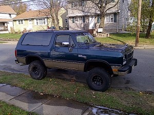
Dodge Ramcharger 1993 Workshop Repair & Service Manual (COMPLETE & INFORMATIVE for DIY REPAIR)

Dodge Ramcharger 1993 Workshop Repair & Service Manual (COMPLETE & INFORMATIVE for DIY REPAIR)

Dodge Ramcharger 1993 Workshop Repair & Service Manual (COMPLETE & INFORMATIVE for DIY REPAIR) ☆ ☆ ☆ ☆ ☆


INSTANT DOWNLOAD


* COMPLETE, Absolutely No Missing Pages!
* Official Service INFORMATION You Can Count On!
* Customer Satisfaction GUARANTEED!

This high QUALITY official manual for Dodge Ramcharger 1993 Pickup is 100 percents COMPLETE and INTACT, no MISSING, CORRUPT pages, sections to freak you out! This manual is exactly as described. It is in the cross-platform PDF document format so that it works like a charm on all kinds of devices.

FORMAT: PDF
LANGUAGE: English
SIZE/PAGE: 1,500 Pages
OS: Windows/Mac OS X/Linux/Android/iOS

MAKE: Dodge
MODEL: D150/D250/D350, W150/W250/W350 RAMCHARGER Rear Wheel Drive Truck
YEAR: 1993 (1981 1982 1983 1984 1985 1986 1987 1988 1989 1990 1991 1992 applicable)

INSTANT DELIVERY: A download link will be sent to you instantly after payment. Simply click on the link and save it to your computer. You can use this Manual as long as you wish with no restrictions.

CUSTOMER SATISFACTION: If there is ANY kind of problem with the item you purchased, just drop a quick email. Within HOURS the issue shall be taken care of.

PRINTABLE MANUAL WITH DIAGRAMS: Just print the manual out and start to work. You can also use the manual with your Tablet/Laptop in your garage.

REFUND/EXCHANGE POLICY: We sell high QUALITY products only. However if you encounter any problems with the item you purchased, another replacement link will be sent to you. If we’re at fault, you will get 100 percents refund.

Buy ☆THE BEST MANUAL ON THE INTERNET☆ from responsible seller and get instant download now without uncertainty or surprise.

This highly detailed workshop service repair manual for download contains virtually everything you will ever need to repair, maintain, rebuild, refurbish or restore Dodge Ramcharger 1993 Truck. All diagnostic and repair procedures and gives you access to the same information that professional technicians and mechanics have. You can view and print out the complete repair procedures with this workshop service repair manual Download – you do not need to be skilled with a computer.

GROUP TAB LOCATOR
Introduction
0 Lubrication and Maintenance
2 Front Suspension and Axle
3 Rear Suspension and Axles
5 Brakes
6 Clutch
7 Cooling System
8 Electrical
9 Engines
11 Exhaust System and Intake Manifold
13 Frame and Bumpers
14 Fuel System
16 Propeller Shafts
19 Steering
21 Transmission and Transfer Case
22 Wheels and Tires
23 B o d y Components
24 Heating and Air Conditioning
25 Emission Control Systems
Component and System Index
Service Manual Comment Forms (Rear of Manual)

TRANSMISSION INSTALLATION—2-WHEEL DRIVE
(1) Apply light coat of Mopar high temperature bearing grease to contact surfaces of following components:
• drive gear splines and pilot bearing hub
• release bearing slide surface of front retainer
• pilot bearing
• release bearing bore
• release fork
• release fork ball stud
• propeller shaft slip yoke
(2) Fill transmission with recommended lubricant.
Correct fill level is bottom edge of fill plug hole.
(3) Mount transmission on jack and position transmission under vehicle.
(4) Raise transmission until drive gear is centered in release bearing and clutch disc hub.
(5) Move transmission forward and start drive gear in release bearing, clutch disc and pilot bushing.
(6) Work transmission forward until seated against clutch housing. Do not allow transmission to remain unsupported after drive gear has entered clutch disc.
(7) Install and tighten transmission-to-clutch housing bolts to 108 N*m (80 ft. lbs.) torque.
(8) Install clutch slave cylinder.
(9) Connect speed sensor and backup light switch wires.
(10) Position transmission harness wires in clips on shift cover.
(11) Install transmission mount on transmission or rear crossmember.
(12) Install rear crossmember.
(13) Remove transmission jack and engine support
fixture.
(14) Align and connect propeller shaft.
(15) Fill transmission with required lubricant, if necessary.
(16) Lower vehicle.
(17) Install shift lever on transmission stub lever.
(18) Install shift boot and bezel.
(19) Connect battery negative cable.

EGR TUBE-GAS POWERED ENGINES
REMOVAL
(1) Remove air filter housing.
(2) Remove the spark plug cable loom and plug cables from valve cover mounting stud at rear of right valve cover. Position spark plug cables to top of valve cover.
(3) Disconnect two vacuum hoses at exhaust gas recirculation (EGR) valve.
(4) Remove 2 EGR valve mounting bolts (Fig. 5) and remove EGR valve. Discard old gasket.
(5) Disconnect electrical connector at engine oil pressure sending unit.
(6) To prevent damage to oil pressure sending unit, a special tool, such as number C-4597 must be used
(Fig. 6). Remove sending unit from engine.
(7) Loosen EGR tube mounting nut at intake manifold (Fig. 7).
Fig. 7 EGR Tube—Typical
(8) Remove EGR tube mounting bolts at exhaust manifold (Fig. 7) and remove EGR tube.
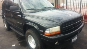
INSTANT DOWNLOAD


Posted on

Dodge Ram 1500-2500-3500 Pickup Truck 1999-2009 Workshop Repair & Service Manual (1.3 GB PDF, COMPLETE & INFORMATIVE for DIY REPAIR) ☆ ☆ ☆ ☆ ☆

Dodge Ram 1500-2500-3500 Pickup Truck 1999-2009 Workshop Repair & Service Manual (1.3 GB PDF, COMPLETE & INFORMATIVE for DIY REPAIR)

INSTANT DOWNLOAD


Dodge Ram 1500-2500-3500 Pickup Truck 1999-2009 Workshop Repair & Service Manual (1.3 GB PDF, COMPLETE & INFORMATIVE for DIY REPAIR) ☆ ☆ ☆ ☆ ☆

* COMPLETE, Absolutely No Missing Pages!
* Official Service INFORMATION You Can Count On!
* Customer Satisfaction GUARANTEED!

This high QUALITY official manual for Dodge Ram 1500-2500-3500 Pickup Truck (incl. SRT-10 & DIESEL) 1999-2009 is 100 percents COMPLETE and INTACT, no MISSING, CORRUPT pages, sections to freak you out! This manual is exactly as described. It is in the cross-platform PDF document format so that it works like a charm on all kinds of devices.

FORMAT: PDF
LANGUAGE: English
SIZE/PAGE: 1,300 MB
OS: Windows/Mac OS X/Linux/Android/iOS

INSTANT DELIVERY: A download link will be sent to you instantly after payment. Simply click on the link and save it to your computer. You can use this Manual as long as you wish with no restrictions.

CUSTOMER SATISFACTION: If there is ANY kind of problem with the item you purchased, just drop a quick email. Within HOURS the issue shall be taken care of.

PRINTABLE MANUAL WITH DIAGRAMS: Just print the manual out and start to work. You can also use the manual with your Tablet/Laptop in your garage.

REFUND/EXCHANGE POLICY: We sell high QUALITY products only. However if you encounter any problems with the item you purchased, another replacement link will be sent to you. If we’re at fault, you will get 100 percents refund.

Buy ☆THE BEST MANUAL ON THE INTERNET☆ from responsible seller and get instant download now without uncertainty or surprise.

This highly detailed workshop service repair manual for download contains virtually everything you will ever need to repair, maintain, rebuild, refurbish or restore Dodge Ram 1500-2500-3500 Pickup Truck 1999 2000 2001 2002 2003 2004 2005 2006 2007 2008 2009. All diagnostic and repair procedures and gives you access to the same information that professional technicians and mechanics have. You can view and print out the complete repair procedures with this workshop service repair manual Download – you do not need to be skilled with a computer.

GROUP TAB LOCATOR
Introduction
0 Lubrication & Maintenance
2 Suspension
3 Differential & Driveline
4 Vehicle Quick Reference
5 Brakes
6 Clutch
7 Cooling
8A Audio/Video
8B Chime/Buzzer
8E Electronic Control Modules
8F Engine Systems
8G Heated Systems
8H Horn
8I Ignition Control
8J Instrument Cluster
8L Lamps
8M Message Systems
8N Power Systems
😯 Restraints
8P Speed Control
8Q Vehicle Theft Security
8R Wipers/Washers
8T Navigation/Telecommunication
8W Wiring
9 Engine
11 Exhaust System
13 Frame & Bumpers
14 Fuel System
19 Steering
21 Transmission and Transfer Case
22 Tires/Wheels
23 Body
24 Heating & Air Conditioning
25 Emissions Control
Component and System Index
DTC Index
Service Manual Comment Forms (Rear of Manual)

BATTERY SYSTEM
DESCRIPTION
GASOLINE ENGINE
Vehicles with a gasoline engine are equipped with a single 12-volt battery. All of the components of the battery system are located within the engine compartment.
The battery system for this vehicle, covers the following related components:
*). Battery (2) – The storage battery provides a reliable means of storing a renewable source of electrical energy within the vehicle.
*). Positive Battery cable (1) – The positive battery cable connects the battery positive terminal post to the vehicle electrical system, starter and alternator.
*). Negative Battery Cable (3) – The negative battery cable connects the battery negative terminal post to the vehicle electrical system through body, chassis and engine grounding points.
*). Battery Thermal Guard (5) – A thermal guard wraps around the battery case to enclose the sides of the battery. The thermal guard consists of a heavy black plastic outer skin and two lighter plies of plastic that have been formed into a sheet with hundreds of small air pockets entrapped between them.
*). Battery Holddown – The battery holddown hardware secures the battery in the battery tray in the engine compartment.
*). Battery Tray – The battery tray provides a secure mounting location in the vehicle for the battery and an anchor point for the battery holddown hardware.
DIESEL ENGINE
Vehicles with a diesel engine utilize two 12-volt batteries connected in parallel. All of the components of the battery system are located within the engine compartment. The battery system for this vehicle, covers the following related components:
*). Left Battery (3) – The Left storage battery provides a reliable means of storing a renewable source of electrical energy within the vehicle.
*). Right Battery (5) – The Right storage battery provides a reliable means of storing a renewable source of electrical energy within the vehicle as well as the additional required electrical energy due to high demands of the diesel system.
*). Positive Battery cables (2 & 6) – The positive battery cables connect the battery positive terminal
posts to the vehicle electrical system, starter and alternator as well as connecting the two batteries together.
*). Negative Battery Cables (1 & 4) – The negative battery cables connect the battery negative terminal posts to the vehicle electrical system through body, chassis and engine grounding points.
*). Battery Thermal Guard – A thermal guard wraps around the battery case to enclose the sides of the battery. The thermal guard consists of a heavy black plastic outer skin and two lighter plies of plastic that have been formed into a sheet with hundreds of small air pockets entrapped between them.

DIFFERENTIAL CASE BEARING PRELOAD AND GEAR BACKLASH
Backlash is adjusted by moving the adjusters in and out or both. By moving the adjusters the case/ring gear will move closer or further away from the pinion.
In most cases this adjustment can be used to achieve the correct gear tooth pattern and set the case bearing
preload.
1. Remove adjuster lock bolts (3) and adjuster locks (2).
2. Loosen the differential bearing cap bolts (4).
3. Slide differential case (1) toward the pinion gear until the gears make contact/zero backlash. If zero backlash cannot be obtained, turn the pinion side adjuster until zero backlash is obtained.
4. Holding the differential case (2) toward the pinion gear, turn bearing adjusters with Adjuster Wrench 8883 (1) until they make contact with the differential bearings/cups.
5. Back off the ring gear side adjuster 4 holes, to obtain initial ring gear backlash.
6. Install ring gear side adjuster lock and bolt. Do not tighten adjuster lock bolt at this time.
7. Tighten pinion gear side adjuster firmly against the differential case bearing cup.
8. Rotate the pinion several times to seat the deferential bearings.
9. Loosen pinion gear side adjuster until it is no longer in contact with the bearing cup, then tighten it until it makes contact.
10. Tighten pinion gear side adjuster an additional:
*). New Bearings: 6 Adjuster Holes
*). Original Bearings: 4 Adjuster Holes
11. Install pinion gear side adjuster lock and bolt.
12. Tighten bearing cap bolts to 165 N·m (122 ft. lbs.).
13. Tighten adjuster lock bolts to 25 N·m (18 ft. lbs.).
14. Measure ring gear (2) backlash with a Dial Indicator C-3339 (1) and Pilot Stud L-4438 at eight points around the drive side of the ring gear. The backlash should be 0.08-0.25 mm (0.003-0.010 in) with a preferred backlash of 0.13-0.18 mm (0.005-0.007 in).


INSTANT DOWNLOAD


Posted on

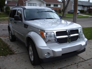
Dodge Nitro 2006-2011 Workshop Repair & Service Manual (4,048 Pages, COMPLETE & INFORMATIVE for DIY REPAIR)

Dodge Nitro 2006-2011

MDGNTR0611NPES.PDF
Price: $9.99 USD

Dodge Nitro 2006-2011 Workshop Repair & Service Manual (4,048 Pages, COMPLETE & INFORMATIVE for DIY REPAIR) ☆ ☆ ☆ ☆ ☆

* COMPLETE, Absolutely No Missing Pages!
* Official Service INFORMATION You Can Count On!
* Customer Satisfaction GUARANTEED!

This high QUALITY official manual for Dodge KA Nitro R/T 2006 2007 2008 2009 2010 2011 is 100 percents COMPLETE and INTACT, no MISSING, CORRUPT pages, sections to freak you out! This manual is exactly as described. It is in the cross-platform PDF document format so that it works like a charm on all kinds of devices.

FORMAT: PDF
LANGUAGE: English
SIZE/PAGE: 4,048 Pages
OS: Windows/Mac OS X/Linux/Android/iOS

INSTANT DELIVERY: A download link will be sent to you instantly after payment. Simply click on the link and save it to your computer. You can use this Manual as long as you wish with no restrictions.

CUSTOMER SATISFACTION: If there is ANY kind of problem with the item you purchased, just drop a quick email. Within HOURS the issue shall be taken care of.

PRINTABLE MANUAL WITH DIAGRAMS: Just print the manual out and start to work. You can also use the manual with your Tablet/Laptop in your garage.

REFUND/EXCHANGE POLICY: We sell high QUALITY products only. However if you encounter any problems with the item you purchased, another replacement link will be sent to you. If we’re at fault, you will get 100 percents refund.

Buy ☆THE BEST MANUAL ON THE INTERNET☆ from responsible seller and get instant download now without uncertainty or surprise.

This highly detailed workshop service repair manual for download contains virtually everything you will ever need to repair, maintain, rebuild, refurbish or restore Dodge Nitro 2006-2011. All diagnostic and repair procedures and gives you access to the same information that professional technicians and mechanics have. You can view and print out the complete repair procedures with this workshop service repair manual Download – you do not need to be skilled with a computer.

├── 3.7L Engine.pdf
├── 4.0L Engine.pdf
├── ABS Electrical.pdf
├── ABS Service.pdf
├── Airbags.pdf
├── Audio Video Electrical.pdf
├── Audio Video.pdf
├── Auto Trans 42RLE Assembly.pdf
├── Auto Trans 42RLE Diagnostic.pdf
├── Auto Trans 42RLE Fluid and Filter.pdf
├── Auto Trans 42RLE Installation.pdf
├── Auto Trans 42RLE Removal.pdf
├── Auto Trans Nag1 Diagnostic and Testing.pdf
├── Auto Trans Nag1 Dissasembly.pdf
├── Auto Trans Nag1 Fluid and Filter.pdf
├── Auto Trans Nag1 Instalation.pdf
├── Auto Trans Nag1 Removal.pdf
├── Auto Trans Nag1 Shifter Diagnosis.pdf
├── Auto Trans Nag1 Torque Converter.pdf
├── Base Service.pdf
├── Body.pdf
├── Clutch.pdf
├── Cooling.pdf
├── Cruise Control.pdf
├── Defogger.pdf
├── Differential and Driveline.pdf
├── Exhaust and Turbo.pdf
├── Exterior Lights Electrical.pdf
├── Exterior Lights.pdf
├── Fuel.pdf
├── HVAC.pdf
├── Heated Mirrors.pdf
├── Hvac Electrical.pdf
├── Ignition Control Electrical.pdf
├── Ignition Control.pdf
├── Instrument Cluster.pdf
├── Manual Trans.pdf
├── Navigation.pdf
├── Overhead Console.pdf
├── Power Locks Electrical.pdf
├── Power Locks.pdf
├── Power Mirrors.pdf
├── Power Seats.pdf
├── Starter.pdf
├── Steering System.pdf
├── Suspension.pdf
├── Transfer Case MP140.pdf
├── Transfer Case MP143.pdf
├── Wiper Washer.pdf
└── Wiring.pdf

EXCERPTS:
HEADLAMPS
The headlamp system includes the SCM, the EMIC, the TIPM, and the left (lighting) multi-function switch on the steering column. The headlamp bulbs have a path to ground at all times through their connection to the engine compartment wire harness. The engine compartment harness has takeouts with eyelet terminals that are secured by nuts to ground studs on the front end sheet metal within the engine compartment. The TIPM will store a Diagnostic Trouble Code (DTC) for any shorts or opens in the headlamp circuits.
The SCM monitors a hard wired multiplex input to determine the status of the left multi-function switch and whether the headlamp high or low beams are selected. The SCM then sends the appropriate electronic headlamp switch and headlamp beam select switch status messages to the EMIC over the LIN data bus. The
EMIC then sends the appropriate electronic headlamp request and headlamp beam request messages to the
TIPM over the CAN data bus. The TIPM responds to these messages by providing a pulse width modulated voltage output to the headlamps through high side drivers on the right and left low and high beam feed circuits to illuminate the selected headlamp filaments. The TIPM also sends the appropriate electronic messages to the EMIC to control the illumination of the high beam indicator. When the optical horn feature is selected, the low beams will shut OFF about 200 milliseconds after the high beams are activated.
The TIPM also remembers which beams (LOW or HIGH) were selected when the headlamps were last turned
OFF, and energizes those beams again the next time the headlamps are turned ON. The TIPM provides a battery saver (load shedding) feature for the headlamps, which will turn these lamps OFF if they are left ON for more than about eight minutes with the ignition switch in the LOCK position. The SCM and the EMIC each provide a
fail-safe feature for the headlamps, which will cause the TIPM to turn the low beam headlamps ON automatically if there is no input available from the left multi-function switch. The TIPM also provides a failsafe feature for the headlamps that will turn the headlamps ON automatically whenever a loss of CAN bus communication is detected with the ignition switch in the ON position.
Each headlamp includes an integral reflector adjustment screw (domestic markets) or screws (export markets) to be used for static aiming of the headlamps.

WATER DRAINAGE AND WIND NOISE DIAGNOSIS
Adequate drainage is provided by a drain trough in the sunroof housing which encircles the sliding glass panel and leads to drain hoses. If a wet headliner or other water leak complaints are encountered, before performing any adjustments, first ensure that the drainage system is not plugged or disconnected. Use a pint container to pour water into the sunroof housing drain trough. If water flow is restricted, use compressed air to blow out any material plugging the drain system. Retest system again.
To further check for a disconnected drain hose:
1. Lower headliner as necessary to gain access to sunroof housing drain tubes. See REMOVAL.
2. Repair as necessary.
3. Install headliner. See INSTALLATION.
The sliding glass panel is designed to seal water entry with a snug fit between the roof and the seal. The fit can be checked by inserting a piece of paper between the roof and the seal. The piece of paper should have some resistance when pulled out when the glass panel is in the closed position. The sunroof housing will drain off a minimum amount of water. Excessive wind noise could result if the gap clearances are exceeded. The sunroof glass panel may need to be adjusted. See ADJUSTMENTS for proper procedures.
DEFLECTOR – SUNROOF WIND
REMOVAL
DEFLECTOR – SUNROOF WIND


MDGNTR0611NPES.PDF
Price: $9.99 USD

Posted on

Dodge Durango 1998-2009 Workshop Repair & Service Manual (456 MB PDF COMPLETE & INFORMATIVE for DIY REPAIR)

Dodge Durango 1998-2009 Workshop Repair & Service Manual (456 MB PDF COMPLETE & INFORMATIVE for DIY REPAIR)

MDGDRG9809OPEK.PDF
Price: $14.99 USD

Dodge Durango 1998-2009 Workshop Repair & Service Manual (456 MB PDF COMPLETE & INFORMATIVE for DIY REPAIR) ☆ ☆ ☆ ☆ ☆

* COMPLETE, Absolutely No Missing Pages!
* Official Service INFORMATION You Can Count On!
* Customer Satisfaction GUARANTEED!

This high QUALITY official manual for Dodge Durango 1998-2009 is 100 percents COMPLETE and INTACT, no MISSING, CORRUPT pages, sections to freak you out! This manual is exactly as described. It is in the cross-platform PDF document format so that it works like a charm on all kinds of devices.

FORMAT: PDF
LANGUAGE: English
SIZE/PAGE: 456 MB
OS: Windows/Mac OS X/Linux/Android/iOS

MAKE: Dodge
YEAR: 1998 1999 2000 2001 2002 2003 2004 2005 2006 2007 2008 2009
MODEL: Durango

INSTANT DELIVERY: A download link will be sent to you instantly after payment. Simply click on the link and save it to your computer. You can use this Manual as long as you wish with no restrictions.

CUSTOMER SATISFACTION: If there is ANY kind of problem with the item you purchased, just drop a quick email. Within HOURS the issue shall be taken care of.

PRINTABLE MANUAL WITH DIAGRAMS: Just print the manual out and start to work. You can also use the manual with your Tablet/Laptop in your garage.

REFUND/EXCHANGE POLICY: We sell high QUALITY products only. However if you encounter any problems with the item you purchased, another replacement link will be sent to you. If we’re at fault, you will get 100 percents refund.

Buy ☆THE BEST MANUAL ON THE INTERNET☆ from responsible seller and get instant download now without uncertainty or surprise.

This highly detailed workshop service repair manual for download contains virtually everything you will ever need to repair, maintain, rebuild, refurbish or restore Dodge Durango 1998-2009. All diagnostic and repair procedures and gives you access to the same information that professional technicians and mechanics have. You can view and print out the complete repair procedures with this workshop service repair manual Download – you do not need to be skilled with a computer.

GROUP TAB LOCATOR
Introduction
0 Lubrication & Maintenance
2 Suspension
3 Differential & Driveline
5 Brakes
7 Cooling
8A Audio
8B Chime/Buzzer
8E Electronic Control Modules
8F Engine Systems
8G Heated Systems
8H Horn
8I Ignition Control
8J Instrument Cluster
8L Lamps
8M Message Systems
8N Power Systems
😯 Restraints
8P Speed Control
8Q Vehicle Theft Security
8R Wipers/Washers
8W Wiring
9 Engine
11 Exhaust System
13 Frame & Bumpers
14 Fuel System
19 Steering
21 Transmission and Transfer Case
22 Tires/Wheels
23 Body
24 Heating & Air Conditioning
25 Emissions Control

Service Manual Comment Forms (Rear of Manual)

FRONT BUMPER
REMOVAL
(1) Open hood.
(2) Support front bumper on a suitable lifting
device.
(3) Disengage wire connectors from fog lamps, if
equipped.
(4) Disengage push-in fasteners attaching air deflector to bottom of bumper fascia.
(5) Remove the bolts attaching the bumper to the inner bumper bracket. (Fig. 1)
(6) Separate front bumper with outer bracket attached from vehicle.

INSTALLATION
When the front bumper is installed, there should be a 19 mm gap between the bumper and front fender.
(1) Place the bumper on a suitable lifting device and position the bumper at the vehicle.
(2) Install the bolts attaching front bumper to inner bumper bracket. Tighten to 94 N·m (70 ft. lbs.) torque.
(3) Install the bolts attaching outer bumper brackets to the frame rail. Tighten to 94 N·m (70 ft. lbs.)torque. Ensure front wheelhouse liners are positioned correctly behind bumper.
(4) Engage wire connectors to fog lamps, if equipped.
(5) Install push-in fasteners attaching air deflector to front bumper fascia.
(6) Remove lifting device.
(7) Close hood.
FRONT FASCIA
REMOVAL
(1) Remove the front bumper. (Refer to 13 – FRAMES & BUMPERS/BUMPERS/FRONT BUMPER – REMOVAL)
(2) Remove the bolts attaching the fascia to the bumper.
(3) Separate fascia from bumper.
INSTALLATION
(1) Position fascia on bumper.
(2) Install the bolts attaching the fascia to the bumper.
(3) Install the front bumper. (Refer to 13 – FRAMES & BUMPERS/BUMPERS/FRONT BUMPER – INSTALLATION)
FRONT INNER BRACKET
REMOVAL
(1) Remove bolts attaching top of bumper to bumper bracket.
(2) Remove nuts attaching inner bumper bracket
to frame (Fig. 1).
(3) Using a shallow socket and extension or equivalent, tap with a hammer to drive inner bumper bracket studs out of frame.
(4) Separate inner bumper bracket from frame.
INSTALLATION
(1) Position inner bumper bracket studs into frame.
(2) Install nuts attaching inner bumper bracket to frame. Tighten nuts to 94 N·m (70 ft. lbs.) torque.
(3) Install bolts attaching top of bumper to bumper bracket.
REAR BUMPER
REMOVAL
(1) Remove trailer hitch, if equipped. (Refer to 13 – FRAMES & BUMPERS/FRAME/TRAILER HITCH – REMOVAL)
(2) Raise and support the rear of the vehicle.
(3) Support the bumper.
(4) Remove rivets at each side rear wheel well.
(5) Disconnect license plate lamp wiring harness.
(6) Remove nuts attaching bumper support brackets
to rear rails and crossmember (Fig. 2).
(7) Remove the bumper/fascia from the vehicle.


MDGDRG9809OPEK.PDF
Price: $14.99 USD

Posted on

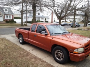
Dodge Dakota 1997-2007 Workshop Repair & Service Manual (COMPLETE & INFORMATIVE for DIY REPAIR) ☆ ☆ ☆ ☆ ☆

Dodge Dakota 1997-2007 Workshop Repair & Service Manual (COMPLETE & INFORMATIVE for DIY REPAIR)

Dodge Dakota 1997-2007 Workshop Repair & Service Manual (COMPLETE & INFORMATIVE for DIY REPAIR) ☆ ☆ ☆ ☆ ☆

MDGDKT9707OPES.PDF
Price: $19.99 USD

* COMPLETE, Absolutely No Missing Pages!
* Official Service INFORMATION You Can Count On!
* Customer Satisfaction GUARANTEED!

This high QUALITY official manual for Dodge Dakota 1997-2007 is 100 percents COMPLETE and INTACT, no MISSING, CORRUPT pages, sections to freak you out! This manual is exactly as described. It is in the cross-platform PDF document format so that it works like a charm on all kinds of devices.

FORMAT: PDF
LANGUAGE: English
SIZE/PAGE: 627 MB
OS: Windows/Mac OS X/Linux/Android/iOS

INSTANT DELIVERY: A download link will be sent to you instantly after payment. Simply click on the link and save it to your computer. You can use this Manual as long as you wish with no restrictions.

CUSTOMER SATISFACTION: If there is ANY kind of problem with the item you purchased, just drop a quick email. Within HOURS the issue shall be taken care of.

PRINTABLE MANUAL WITH DIAGRAMS: Just print the manual out and start to work. You can also use the manual with your Tablet/Laptop in your garage.

REFUND/EXCHANGE POLICY: We sell high QUALITY products only. However if you encounter any problems with the item you purchased, another replacement link will be sent to you. If we’re at fault, you will get 100 percents refund.

Buy ☆THE BEST MANUAL ON THE INTERNET☆ from responsible seller and get instant download now without uncertainty or surprise.

This highly detailed workshop service repair manual for download contains virtually everything you will ever need to repair, maintain, rebuild, refurbish or restore Dodge Dakota 1997-2007. All diagnostic and repair procedures and gives you access to the same information that professional technicians and mechanics have. You can view and print out the complete repair procedures with this workshop service repair manual Download – you do not need to be skilled with a computer.

EXCERTS:
GROUP TAB LOCATOR
Introduction
0 Lubrication & Maintenance
2 Suspension
3 Differential & Driveline
5 Brakes
6 Clutch
7 Cooling
8A Audio/Video
8B Chime/Buzzer
8E Electronic Control Modules
8F Engine Systems
8G Heated Systems
8H Horn
8I Ignition Control
8J Instrument Cluster
8L Lamps
8M Message Systems
8N Power Systems
😯 Restraints
8P Speed Control
8Q Vehicle Theft Security
8R Wipers/Washers
8T Navigation/Telecommunication
8W Wiring
9 Engine
11 Exhaust System
13 Frame & Bumpers
14 Fuel System
19 Steering
21 Transmission and Transfer Case
22 Tires/Wheels
23 Body
24 Heating & Air Conditioning
25 Emissions Control
Component and System Index
DTC Index

BACKLITE
REMOVAL
CAUTION: It is difficult to salvage the backlite during the removal operation. The backlite is part of the structural support for the roof. The urethane bonding used to secure the glass to the fence is difficult to cut or clean from any surface. Since the molding is set in urethane, it is unlikely it would be salvaged. Before removing the backlite, check the availability from the parts supplier.
NOTE: The backlite is attached to the window frame with urethane adhesive. The urethane adhesive is applied cold and seals the surface area between the window opening and the glass. The primer adheres the urethane adhesive to the backlite.
1. Roll down door glass.
2. Remove headliner (9) (Refer to 23 – BODY/INTERIOR/ HEADLINER – REMOVAL).
3. On club cab models remove the upper c-pillar trim (2). (Refer to 23 – BODY/INTERIOR/PANEL-C PILLAR UPPER TRIM – REMOVAL)
4. On quad cab models remove the upper c-pillar trim (2). (Refer to 23 – BODY/INTERIOR/PANEL-C PILLAR UPPER TRIM – REMOVAL)
5. Disconnect the rear window defogger electrical connector (1), if equipped.
6. Bend backlite retaining tabs (2) inward against glass.
7. Using a suitable pneumatic knife from inside the vehicle, cut urethane holding backlite frame to opening fence.
8. Separate glass (1) from vehicle.

SENSOR-CRANKSHAFT POSITION
DESCRIPTION
3.7L V-6
The Crankshaft Position (CKP) sensor (2) is mounted into the right rear side of the cylinder block. It is positioned and bolted into a machined hole.
4.7L V-8
The Crankshaft Position (CKP) sensor (1) is mounted into the right rear side of the cylinder block. It is positioned and bolted into a machined hole.

OPERATION
3.7L V-6
Engine speed and crankshaft position are provided through the CKP (Crankshaft Position) sensor. The sensor generates pulses that are the input sent to the Powertrain Control Module (PCM). The PCM interprets the sensor input to determine the crankshaft position.
The PCM then uses this position, along with other inputs, to determine injector sequence and ignition timing.
The sensor (3) is a hall effect device combined with an internal magnet. It is also sensitive to steel within a certain distance from it. A tonewheel (targetwheel) is bolted to the engine
crankshaft (1). This tonewheel has sets of notches (2) at its outer edge. The notches cause a pulse to be generated when they pass under the sensor. The pulses are the input to the
PCM.

Dodge Dakota 1997-2007 Workshop Repair & Service Manual (COMPLETE & INFORMATIVE for DIY REPAIR) ☆ ☆ ☆ ☆ ☆

MDGDKT9707OPES.PDF
Price: $19.99 USD