Posted on

New Holland TC5040, TC5050, TC5060, TC5070, TC5080 Hillside Combines Factory Service & Shop Manual


Download Link

INSTANT DOWNLOAD (add to cart)

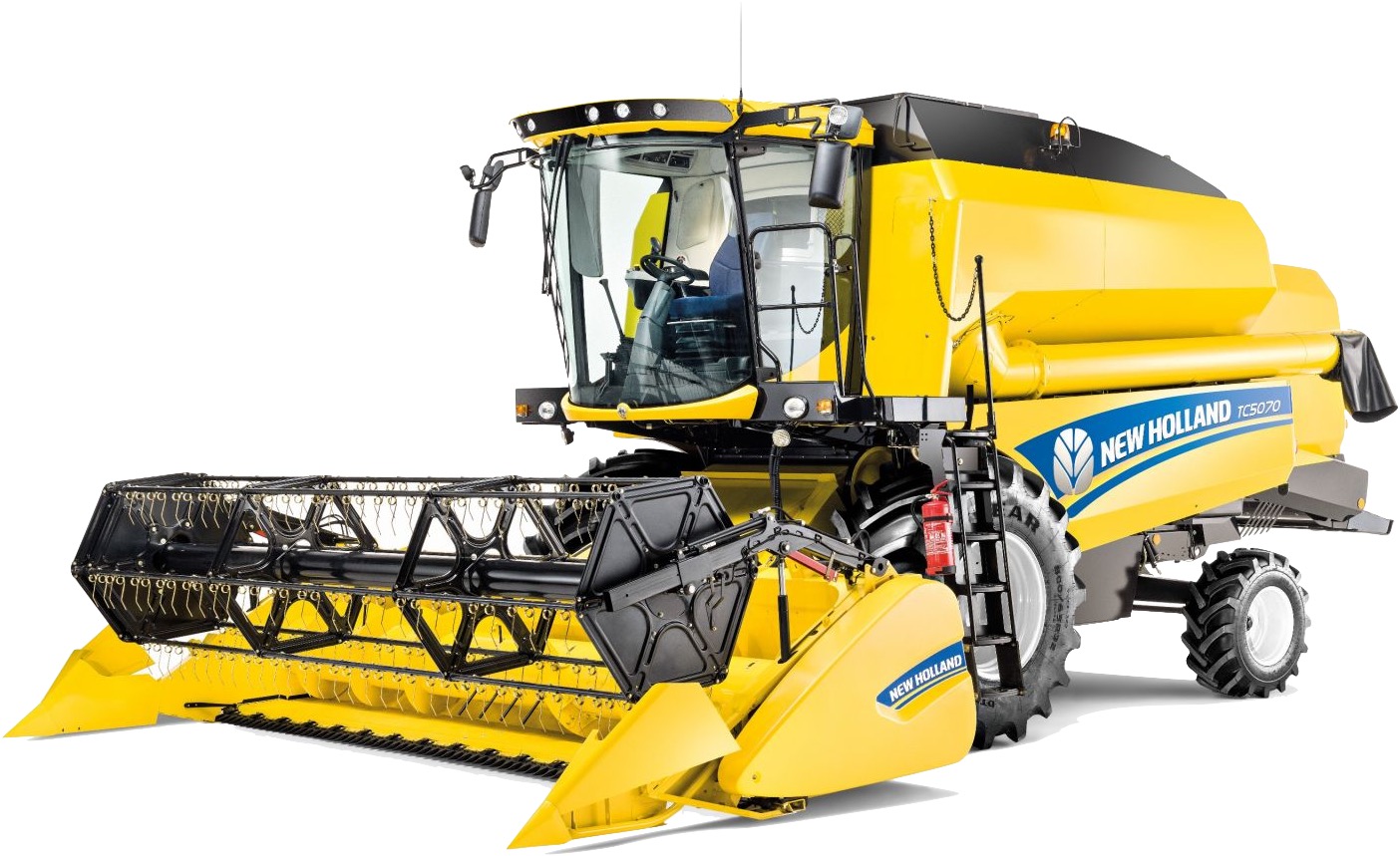
Complete workshop & service manual with electrical wiring diagrams for New Holland TC5040, TC5050, TC5060, TC5070, TC5080 Hillside Combines. It’s the same service manual used by dealers that guaranteed to be fully functional and intact without any missing page.

New Holland TC5040, TC5050, TC5060, TC5070, TC5080 Hillside Combines service & repair manual (including maintenance, overhaul, disassembling & assembling, adjustment, tune-up, operation, inspecting, diagnostic & troubleshooting…) is divided into different sections. Each section covers a specific component or system with detailed illustrations. A table of contents is placed at the beginning of each section. Pages are easily found by category, and each page is expandable for great detail. The printer-ready PDF documents work like a charm on all kinds of devices.

1,431 pages, bookmarked, Searchable, Printable, high quality PDF
84565976A – TC5040, TC5050, TC5060, TC5070, TC5080 Service Manual.pdf

EXCERPT:
Contents
INTRODUCTION
Engine… 10
Engine air compressor . . 10.450
Clutch … 18
Clutch hydraulic release control . . 18.104
Clutch and components . . 18.110
Transmission…… 21
Mechanical transmission . . . 21.114
Mechanical transmission external controls . . . 21.130
Gearbox . . 21.120
Gearbox internal components . . 21.145
Differential . . 21.182
Front axle system ……….. 25
Final drives . . . 25.310
Rear axle system………… 27
Planetary and final drives. . . 27.120
Hydrostatic drive…………. 29
Transmission and steering hydrostatic control . . . 29.100
Reservoir, cooler, and lines. . . 29.204
Pump and motor components . . 29.218
Hydrostatic transmission . . . 29.202
Rear hydrostatic transmission . . 29.300
Brakes and controls …….. 33
Hydraulic service brakes . . . 33.202
Parking brake. . . 33.110
Hydraulic systems……….. 35
Hydraulic systems . . 35.000
Reservoir, cooler, and filters . . 35.300
Variable displacement pump . . . 35.106
Main control valve . . 35.359
Remote control valves. . 35.204
Machine leveling control system . . . 35.610
Machine lateral leveling system . . 35.630
Machine longitudinal leveling system. . . 35.640
Header/Attachment leveling system. . 35.602
Reel control system . . 35.518
Steering…………. 41
Hydraulic control components . . 41.200
Pump . . . 41.206
Cylinders . . . 41.216
Cab climate control ……… 50
Air conditioning . . . 50.200
Electrical systems ……….. 55
Electrical system . . . 55.000
Harnesses and connectors . . . 55.100
Selective Catalytic Reduction (SCR) electrical system. . . 55.988
Electronic modules . . . 55.640
Cab Heating, Ventilation, and Air-Conditioning (HVAC) controls . . . 55.051
Heating, Ventilation, and Air-Conditioning (HVAC) control system . . . 55.050
Sieve electric control . . . 55.834
Precision farming system. . . 55.785
FAULT CODES . . 55.DTC
Attachments/Headers…… 58
Attachment/Header reel . . 58.101
Belt feeding . . . 58.900
Product feeding .. 60
Feed roll . . 60.101
Floating roll, feed chain, and drive . . . 60.105
Feeder drive system. . 60.150
Length-of-cut gearbox . . 60.122
Threshing ………. 66
Threshing . . . 66.000
Drum. . 66.330
Drum/Rotor variator with electrical control . . . 66.321
Concave . . 66.105
Separation ……… 72
Beater . . 72.350
Straw walkers and shafts . . . 72.101
Residue handling…….. 73
Straw chopper drive system . . 73.210
Straw chopper electromagnetic clutch support . . . 73.215
Cleaning ………… 74
Cleaning . . 74.000
Cleaning drive systems. . . 74.101
Grain pan . . . 74.110
Upper shaker shoe . . . 74.114
Lower shaker shoe . . . 74.118
Fan housing . . 74.130
Fan drive system . . . 74.136
Tailings return system . . 74.140
Crop storage / Unloading …………. 80
Clean grain elevator . . 80.101
Platform, cab, bodywork, and decals ……… 90
Cab doors and hatches. . . 90.154

Posted on

New Holland T9010/T9020/T9030/T9040/T9050/T9060 Tractors Factory Service & Shop Manual


Download Link

INSTANT DOWNLOAD (add to cart)


Complete workshop & service manual with electrical wiring diagrams for New Holland T9000 Series (T9010, T9020, T9030, T9040, T9050, T9060) Tractors. It’s the same service manual used by dealers that guaranteed to be fully functional and intact without any missing page.

New Holland T9010, T9020, T9030, T9040, T9050, T9060 service & repair manual (including maintenance, overhaul, disassembling & assembling, adjustment, tune-up, operation, inspecting, diagnostic & troubleshooting…) is divided into different sections. Each section covers a specific component or system with detailed illustrations. A table of contents is placed at the beginning of each section. Pages are easily found by category, and each page is expandable for great detail. The printer-ready PDF documents work like a charm on all kinds of devices.

2,667 pages, bookmarked, Searchable, Printable, high quality PDF

“Repair manual.pdf”
New Holland T9000 Series (T9010/T9020/T9030/T9040/T9050/T9060) Tractors Repair Manual
2,378 pages

NOTE: Engine repair information is not contained within this tractor Repair Manual. For engine repair, refer to appropriate engine repair manual as follows:
87515682 – For 8.3 & 9.0L 6 Cylinder, 24 Valve CNH Engine with High Pressure Common Rail Fuel System. 87523643 – For 12.9L 6 Cylinder, Engine.

“87562838.pdf”
New Holland T9010/T9020/T9030/T9040/T9050/T9060 Tractors Operator’s Manual
87562838 8/06 Replaces 87399833
284 pages

“87517740.pdf”
T9010, 9020, 9030, 9040, 9050, 9060 Series Tractors For Powershift Transmissions Euro Electrical Schematic

“87522497.pdf”
NAO Tj 280, 330, 380, 430, 480 And 530 Series Tractors & Euro T9010, 20, 30, 40, 50 And 60 Series Tractors Hydraulic Schematics Equipped With Megaflow Rac. 87522497

EXCERPT:
Section 21 – Transmissions, Drivelines – Chapter 1
TRANSMISSION REMOVAL
STEP 1
Refer to Cab Removal and Installation in this manual and remove the hood.
STEP 2
To drain the transmission, slowly loosen the split flange bolts on the lubrication pump suction tube.
Control the flow by tightening or loosening the bolts.
NOTE: The transmission fluid capacity is approximately 38 to 45 litres (10 to 12 gallons).
When the transmission is completely drained. Remove the split flange bolts and the retainers.
STEP 3
Remove the fill tube from the transmission.
STEP 4
Remove the four nuts and two bolts to remove the rear axle driveshaft cover.
STEP 5
Remove the rear axle intermediate driveshaft from the transmission output yoke. Move the driveshaft rearward away from the transmission.
STEP 6
If equipped, remove the driveshaft from the PTO MK99J255 Remove the front frame wire harness connector from clutch output yoke.

Posted on

New Holland / Ford T8010, T8020, T8030, T8040 Tractors Factory Service & Shop Manual


Download Link

INSTANT DOWNLOAD (add to cart)


Complete workshop & service manual with electrical wiring diagrams for New Holland / Ford T8010, T8020, T8030, T8040 Tractors. It’s the same service manual used by dealers that guaranteed to be fully functional and intact without any missing page.

This New Holland / Ford T8010, T8020, T8030, T8040 Tractors service & repair manual (including maintenance, overhaul, disassembling & assembling, adjustment, tune-up, operation, inspecting, diagnostic & troubleshooting…) is divided into different sections. Each section covers a specific component or system with detailed illustrations. A table of contents is placed at the beginning of each section. Pages are easily found by category, and each page is expandable for great detail. The printer-ready PDF documents work like a charm on all kinds of devices.

2,981 pages, bookmarked, Searchable, Printable, high quality PDF

FILELIST:
603.69.770.50 – Flat Time Rate Manual & Fault Code (T8010, T8020, T8030, T8040).pdf
87389711 – T8010, T8020, T8030, T8040 Tractors EURO Electrical Schematic.pdf
87518877 – T8000 Series (T8010, T8020, T8030, T8040) EURO Hydraulic Schematic with Hydraulic Trailer Brakes & Megaflow.pdf
87573022 (Replaces 87393897) – T8010, T8020, T8030, T8040 Operators Manual.pdf
87588603 – T8000 Series (T8010, T8020, T8030, T8040) EURO Electrical Schematic (PIN Z6RW04001 & after).pdf
T8000 Series Tractor Operators Manual.pdf
T8010, T8020, T8030, T8040 Repair Manual.pdf

EXCERPT:
Section 21 – Transmission, Drivelines – Chapter 4
SPEED TRANSMISSION WITH CREEP OPTION
STEP 1
1. INPUT SHAFT
2. OUTPUT SHAFT
3. COUNTERSHAFT
Remove the mounting bolts from the front bearing support cover.
STEP 2
Use prybars under the two lift areas in the front bearing support cover and loosen the cover.
NOTE: Cover is shown without creep option. Prybars must be in same lift areas for covers with or without creep option.
STEP 3
Remove any remaining seal material from the bolt hole threads. Install two bolts in the bearing support cover at the 1 and 7 o’clock position (front view
shown). Tighten bolts only finger-tight.
NOTE: Use Steps 4 through 6 for transmission equipped with the creep option. Use Steps 8 through 11 for transmissions without the creep option.
STEP 4
Make support blocks as follows:
1. Use suitable material to make two support blocks that will hold at least 400 lb (181 kg).
2. One block must be 14 inch H x 10 inch L x 2-3/4 inch W.
3. The other block must be 14 inch H x 4-1/2 inch L x 2-1/4 W.
Countershaft, Input Shaft, And Output Shaft Removal For Transmissions With Creep Option
STEP 5
Remove housing as follows:
1. Connect a chain to the rear of the speed housing (shown with cab mounting bracket attached).
2. Use a suitable hoist to remove the housing from the engine stand.
3. Raise the housing up enough to put the support blocks in position under the bearing support cover as shown above.
4. Slowly lower the transmission housing until the bearing support cover is fully seated on the support blocks.
NOTE: Be sure the blocks are in the correct position on the support cover.
5. Reach under the housing and remove the two remaining support cover retaining bolts that were tightened only finger tight.
STEP 6
Slowly raise the transmission housing leaving the bearing support cover and three shaft assemblies on
the support blocks.
STEP 7
Remove the mounting bolts from the three bearing cages. Remove the bearing cages and shims.
NOTE: Keep the shims together with the bearing cage as the cages are removed.

Posted on

New Holland T5030, T5040, T5050, T5060 Tractors Factory Service & Shop Manual


Download Link

INSTANT DOWNLOAD (add to cart)


Complete workshop & service manual with electrical wiring diagrams for New Holland Tractors T5030, T5040, T5050, T5060. It’s the same service manual used by dealers that guaranteed to be fully functional and intact without any missing page.

This New Holland T5030, T5040, T5050, T5060 service & repair manual (including maintenance, overhaul, disassembling & assembling, adjustment, tune-up, operation, inspecting, diagnostic & troubleshooting…) is divided into different sections. Each section covers a specific component or system with detailed illustrations. A table of contents is placed at the beginning of each section. Pages are easily found by category, and each page is expandable for great detail. The printer-ready PDF documents work like a charm on all kinds of devices.

1,685 pages, bookmarked, Searchable, Printable, high quality PDF
New Holland T5030, T5040, T5050, T5060 Tractors Service Manual
Print No. 87679925A – 12 – 2007

EXCERPT:

18 SECTION 27 – REAR AXLE MECHANICAL TRANSMISSION – CHAPTER 1

DESCRIPTION AND OPERATION

The rear transmission transmits drive from the gearbox to the final drives by means of the bevel drive, the teeth on the bevel drive are helical supported on tapered roller bearings.

The differential has two planet gears and is fitted with a mechanically or hydraulically operated differential lock.
Operation of this device is described below.

The final drives are of the epicyclical type and are operated by the bevel drive output half shafts, the same shafts that control the service brakes.

HYDRAULICALLY CONTROLLED REAR DIFFERENTIAL LOCK

When the differential lock is not being used, it is held in the disengaged position by the pressure of the spring (4) on the fork (3).

By operating the relative switch on the control panel, the solenoid valve opens to allow the oil sent from the pump to enter the chamber (1). After acting on the piston (2) and spring (4), it moves rod (5), fork (3) and the sleeve, thereby engaging the differential lock. When the switch is pressed to disengage the differential lock, spring (4) exerts a force on fork (3), rod (5) and piston (2), which discharges the oil through the corresponding solenoid valve.

Posted on

New Holland Tractors T3010, T3020, T3030, T3040 Factory Service & Shop Manual


Download Link

INSTANT DOWNLOAD (add to cart)

Complete workshop & service manual with electrical wiring diagrams for New Holland Tractors 3010, 3020, 3030, 3040. It’s the same service manual used by dealers that guaranteed to be fully functional and intact without any missing page.

This New Holland Tractors 3010, 3020, 3030, 3040 service & repair manual (including maintenance, overhaul, disassembling & assembling, adjustment, tune-up, operation, inspecting, diagnostic & troubleshooting…) is divided into different sections. Each section covers a specific component or system with detailed illustrations. A table of contents is placed at the beginning of each section. Pages are easily found by category, and each page is expandable for great detail. The printer-ready PDF documents work like a charm on all kinds of devices.
4,263 + 4,800 pages, bookmarked, Searchable, Printable, high quality PDF
FILELIST:
84183229B – T3010_3020_3030_3040 Tractors Service Manual.pdf
87289563 – T3010_3020_3030_3040 Tractors Operator’s Manual (Operation – Maintenance – Specifications).pdf
87290735 – T3010_3020_3030_3040 Tractors Operator’s Manual.pdf
87291123 – T3010_3020_3030_3040 Tractors Operator’s Manual.pdf
87471759 – Section50_Climate Control & Section55_Electrical System.pdf

EXCERPT:
T3010 — T3020 — T3030 — T3040
SERVICE MANUAL
SECTIONS
SECTION GENERAL GUIDELINES . . 00
SECTION ENGINE . . 10
SECTION CLUTCH . . 18
SECTION TRANSMISSIONS . . 21
SECTION FRONT MECHANICAL TRANSMISSION . . . 25
SECTION REAR MECHANICAL TRANSMISSION . . 27
SECTION POWER TAKE–OFF . . . 31
SECTION BRAKES . . . . 33
SECTION HYDRAULIC SYSTEMS . . . 35
SECTION STEERING . . . 41
SECTION CAB AIR CONDITIONING SYSTEM . . . . 50
SECTION ELECTRICAL SYSTEM . . . 55
SECTION CAB . . 90

SECTION 35 — HYDRAULIC SYSTEMS — CHAPTER 1 5
84183229A — 01 — 2009
DESCRIPTION AND OPERATION (fig. 2)
— A. Position control (lever 1).
POSITION CONTROL operation permits correspondence between the position of the control lever (1) and the position of the lifting arms.
It is obtained by turning the draft control lever (2) clockwise against the catch (B). The position of the implement is determined, in or out of the ground, by moving the lever (1) anticlockwise against the catch (A) for raising and clockwise against the catch (B) for lowering.
— B. Draft control (lever 2).
DRAFT CONTROL operation permits adjusting the working depth associated with the draft required of the tractor, thus making a constant working depth possible on undulating ground.
It is accomplished by moving the position control lever (1) against the catch (B), the implement enters the ground at the desired depth by gradually moving the lever (2) towards the catch (B). This operation makes each position of the lever (2) correspond to a certain draft or compression on the three point hitch.
The depth reached by the implement is proportional to the traction power which, in turn, is determined by the firmness of the ground. In these conditions, the lift will automatically maintain the traction power required from the tractor at a constant level.
On determining the working depth, it is necessary to leave the draft control lever (2) alone and raise the implement at each headland by using only the position control lever (1).
There is a change in working depth when the firmness of the ground changes, it is possible to use the draft lever (2) to go back into the desired condition.
With both levers against the catch (B) there is a float function of the lifting arms (the cylinder is connected with the exhaust), the lift no longer works with draft control.
— C. Mixed position and draft control.
MIXED POSITION AND DRAFT CONTROL
Operation is useful when the ground is not even. This adjustment makes the lift work as in the case with draft control, but at the same time it prevents the implement, on meeting patches of ground with less resistance, from going too deep making the work uneven.
The implement enters the ground and the desired working depth is searched for as described for draft control. On reaching the desired depth, gradually turn the lever (1) towards the catch (A) so the lift arms tend to raise slightly.
To raise and make the implement enter the ground at each headland, use only the position control lever (1), then moving it back into the previously determined position.
NOTE: In the three above–described types of operation, sometimes it is helpful to adjust the implement down speed, and this is possible by screwing in the control valve slide adjuster (RD fig. 21) until the desired down speed is obtained.
Fully screwing on the adjuster (RD fig. 21) locks the arms even when lowering the control levers (1) and (2).
It is advisable to use the lock during transport and when stopping with the implement raised.
FLOAT SETTING
To work in float function move both levers (1 and 2, fig. 22) fully downwards.
The float function allows the lift arms to move freely within their travel limits.