Posted on

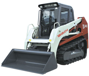
Takeuchi Crawler Loader TL140 Factory Service & Shop Manual


Download Link

INSTANT DOWNLOAD (add to cart)

Complete workshop & service manual with electrical wiring diagrams for Takeuchi Crawler Loader TL140. It’s the same service manual used by dealers that guaranteed to be fully functional and intact without any missing page.

This Takeuchi Crawler Loader TL140 service & repair manual (including maintenance, overhaul, disassembling & assembling, adjustment, tune-up, operation, inspecting, diagnostic & troubleshooting…) is divided into different sections. Each section covers a specific component or system with detailed illustrations. A table of contents is placed at the beginning of each section. Pages are easily found by category, and each page is expandable for great detail. The printer-ready PDF documents work like a charm on all kinds of devices.

559 pages, bookmarked, Searchable, Printable, high quality PDF
Takeuchi Crawler Loader TL140 Workshop Manual; 559 pages; Serial Number: 21400011~.

EXCERPT:
CONTROL VALVE – HYDRAULIC UNITS
DISASSEMBLY AND ASSEMBLY General Cautions
• Since all parts in control valves are precision machined, carry out disassembly and assembly operations in a clean place.
• Before disassembly, clean the outside surfaces around the valves.
• Clean all disassembled parts in cleaning solvent. Use a lint free cloth, or air dry the parts.
• Apply hydraulic oil to sliding surfaces and apply a thin coating of grease to seals when assembling them.
Following is an explanation of the control valve disassembly procedure.
Follow the procedure used to disassemble the control valve in reverse order when reassembling it.
Disassembly
Valve Assembly
1. Loosen the nuts and remove the tie rods, then remove the sections.
Nut: 39.23 ±3.92 N·m
2. Remove the O-ring.
• The mating surfaces are metal seals, so be
careful not to scratch, bruise or otherwise dam- age them.

Posted on

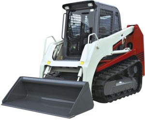
Takeuchi Crawler Loader TL130 Factory Service & Shop Manual


Download Link

INSTANT DOWNLOAD (add to cart)

Complete workshop & service manual with electrical wiring diagrams for Takeuchi Crawler Loader TL130. It’s the same service manual used by dealers that guaranteed to be fully functional and intact without any missing page.

This Takeuchi Crawler Loader TL130 service & repair manual (including maintenance, overhaul, disassembling & assembling, adjustment, tune-up, operation, inspecting, diagnostic & troubleshooting…) is divided into different sections. Each section covers a specific component or system with detailed illustrations. A table of contents is placed at the beginning of each section. Pages are easily found by category, and each page is expandable for great detail. The printer-ready PDF documents work like a charm on all kinds of devices.

712 pages, bookmarked, Searchable, Printable, high quality PDF
Takeuchi Crawler Loader TL130 Workshop Manual; 712 pages; Serial Number: 21300004~.

EXCERPT:
I . GENERAL
II . SPECIFICATIONS
III. MACHINE CONFIGURATION
IV . HYDRAULIC UNITS
V . TROUBLESHOOTING VI. ENGINE

HYDRAULIC UNITS – HST PUMP
2. Remove the charge relief valve.
a. Before removing the screw adjustable relief
valve plug, mark the plug, lock nut (5), and housing so as to approximately maintain the original adjustment when assembling. Remove the screw adjustable charge relief valve plug (6) by loosening the lock nut and unscrewing the plug. Remove the O-ring from the plug (6).
b. Remove the spring (7) and poppet (8) from the housing.
3. Remove the flushing valve.
a. Remove the flushing valve plug (9) from the pump housing. Remove the O-ring from the plug (9).
b. Remove the flushing valve spool (10) assembly from the housing.
4. Remove the flushing relief valve.
a. Remove the flushing relief valve internal hex plug (11) from the pump housing. Remove the O-ring from the plug (11).
b. Remove the spring (13) and poppet (14) from the housing.
c. Do not alter the shims (12) which are installed between the spring and valve plug, or inter- change parts with another valve.

Posted on

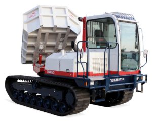
Takeuchi Dump Carrier TCR50 Factory Service & Shop Manual


Download Link

INSTANT DOWNLOAD (add to cart)


Complete workshop & service manual with electrical wiring diagrams for Takeuchi Dump Carrier TCR50. It’s the same service manual used by dealers that guaranteed to be fully functional and intact without any missing page.

This Takeuchi Dump Carrier TCR50 service & repair manual (including maintenance, overhaul, disassembling & assembling, adjustment, tune-up, operation, inspecting, diagnostic & troubleshooting…) is divided into different sections. Each section covers a specific component or system with detailed illustrations. A table of contents is placed at the beginning of each section. Pages are easily found by category, and each page is expandable for great detail. The printer-ready PDF documents work like a charm on all kinds of devices.

302 pages, bookmarked, Searchable, Printable, high quality PDF
Takeuchi Dump Carrier TCR50 Workshop Manual; 302 pages; Serial Number: 30500003~ 30500038~ 30510001~.

EXCERPT:
5. HYDRAULIC SYSTEM
. Remove the swash plate as follows:
Remove the swash plate (10).
• Take care not to damage the sliding surface of the swash plate.
9. Remove the needle bearing assembly as follows: Remove the needle bearing assembly (12) from the servo piston.
10. Remove the valve plate as follows:
Remove the valve plate (13) from the housing.
• If the valve plate is hard to remove, use a flat head driver.
• Take care not to damage the valve plate.
11. Remove the timing pin.
Remove the timing pin (14) of the valve plate.
12. Remove the servo cover (15) as follows:
(1) Remove the five cap screws.
(2) Remove the servo cover (15) and gasket (17).

Posted on

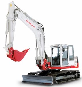
Takeuchi Compact Excavator TB1140 Factory Service & Shop Manual


Download Link

INSTANT DOWNLOAD (add to cart)


Complete workshop & service manual with electrical wiring diagrams for Takeuchi Compact Excavator TB1140. It’s the same service manual used by dealers that guaranteed to be fully functional and intact without any missing page.

This Takeuchi Compact Excavator TB1140 service & repair manual (including maintenance, overhaul, disassembling & assembling, adjustment, tune-up, operation, inspecting, diagnostic & troubleshooting…) is divided into different sections. Each section covers a specific component or system with detailed illustrations. A table of contents is placed at the beginning of each section. Pages are easily found by category, and each page is expandable for great detail. The printer-ready PDF documents work like a charm on all kinds of devices.

652 pages, bookmarked, Searchable, Printable, high quality PDF
Takeuchi Compact Excavator TB1140 Workshop Manual; 652 pages; Serial Number: 51400007~.

EXCERPT:
I . GENERAL
II . SPECIFICATIONS
III. MACHINE CONFIGURATION
IV . HYDRAULIC UNITS
V . TROUBLESHOOTING VI. ENGINE

UPPER FRAME – MACHINE CONFIGURATION
Removing the Cab
1. Disconnect the battery ground cable from the battery.
2. Remove the operator seat from the bracket.
3. Remove the cover R (1), L (2) and C (3), then remove bracket (4) from cover C (3).
4. Remove the cover R (5), then disconnect the speaker cords.
5. Remove the cover L (6), then disconnect the speaker cords and duct hose (7) from cover L (6).
6. Remove the duct hose (8) from air conditioner unit (9)
7. Remove the installation bolts, remove the box (10) from cab.
8. Disconnect the wiring (11) to the cab.
9. Disconnect the hose (12) from sub tank.
10. Loosen the seat bracket installation bolts (13) [four].
11. Remove installation bolts (14) [six], then hoist and remove the cab.
• Be sure to hoist the cab carefully by sliding the seat so as not to hit the cab. Cab: 370 kg
Installing the Cab
Follow the procedure used for removal in reverse order.
• Suspend the cab temporarily, keeping it level, and fasten it temporarily while it is still suspended.

Posted on

Takeuchi Compact Excavator TB180FR Factory Service & Shop Manual


Download Link

INSTANT DOWNLOAD (add to cart)

Complete workshop & service manual with electrical wiring diagrams for Takeuchi Compact Excavator TB180FR. It’s the same service manual used by dealers that guaranteed to be fully functional and intact without any missing page.

This Takeuchi Compact Excavator TB180FR service & repair manual (including maintenance, overhaul, disassembling & assembling, adjustment, tune-up, operation, inspecting, diagnostic & troubleshooting…) is divided into different sections. Each section covers a specific component or system with detailed illustrations. A table of contents is placed at the beginning of each section. Pages are easily found by category, and each page is expandable for great detail. The printer-ready PDF documents work like a charm on all kinds of devices.

686 pages, bookmarked, Searchable, Printable, high quality PDF
Takeuchi Compact Excavator TB180FR Workshop Manual; 686 pages; Serial Number: 17830004~.

EXCERPT:
I . GENERAL
II . SPECIFICATIONS
III. MACHINE CONFIGURATION IV. HYDRAULIC UNITS
V . TROUBLESHOOTING VI. ENGINE

HYDRAULIC UNITS – HYDRAULIC PUMP
Assembly
1. Install the set screw (2).
• Fix the set screw (2) to the same length as previously assembled using the lock nut (3). Lock Nut: 98 N·m
2. Install the piston.
3. Install the drain plug (1).
4. Install the oil seal.
5. Install the shaft in the housing.
• Tap the spline end with a plastic hammer to positively install the outer race of the bearing in the housing hole.
6. Fit the pin R and L on the swash plate.
7. Install the swash plate in the housing.
• Insert the bushing into the swash plate.
• Apply grease on the sliding surfaces of the swash plate, pin R and pin L.
8. Mount the pin and tighten the plug. Plug: 110 N·m.
9. Mount the piston in the housing.