John Deere John Deer 2140 Tractor Operator’s Manual
OML34755 G0 – John Deer 2140 Tractor Operator’s Manual.pdf
OML37119 H1 – John Deer 2140 Tractor (from SN 430,000 L) Operator’s Manual.pdf
OML40936 J5 – John Deer 2140 Tractor (form SN450,000 L) Operator’s Manual.pdf
402 pages, bookmarked, Searchable, Printable, high quality PDF
Complete Operator’s Manuals for John Deere John Deer 2140 Tractor. It’s the same service manual used by dealers that guaranteed to be fully functional and intact without any missing page.
This John Deere John Deer 2140 Tractor Operator’s Manual is divided into different sections. Each section covers a specific component or system with detailed illustrations. A table of contents is placed at the beginning of each section. Pages are easily found by category, and each page is expandable for great detail. The printer-ready PDF documents work like a charm on all kinds of devices.
TM4373 – John Deer 2140 Tractor Technical manual.pdf
1,236 pages, bookmarked, Searchable, Printable, high quality PDF
Complete technical Operation & Test Manual with electrical wiring diagrams for John Deere 2140 Tractor. It’s the same service manual used by dealers that guaranteed to be fully functional and intact without any missing page.
John Deere 2140 Tractor Technical Manual (including maintenance, overhaul, disassembling & assembling, adjustment, tune-up, operation, inspecting, diagnostic & troubleshooting…) is divided into different sections. Each section covers a specific component or system with detailed illustrations. A table of contents is placed at the beginning of each section. Pages are easily found by category, and each page is expandable for great detail. The printer-ready PDF documents work like a charm on all kinds of devices.
CONTENTS
10- GENERAL
00- Specifications and special tools
05- Pre-delivery, delivery and after-sales inspections
10- Lubrication and periodic service
15- Engine and tractor tune-up
20- Tractor separation (tractors without increased lift capacity)
25 – Tractor separation (tractors with increased lift capacity)
SECTION 20- ENGINE
Group 00- Specifications
Group 05- Radiator
FUEL AND AIR INTAKE SYSTEM
Specifications and special tools
General information, diagnosing malfunctions
Fuel tank and water trap
Cold weather starting aids
Speed control linkage
Air cleaner
Group 35 – ELECTRICAL SYSTEM
Specifications and special tools
Description, diagnosing malfunctions and tests
Wiring harnesses
Controls and instruments
Lighting systems
Wiring diagrams
Starting motor
Alternator
Group 60- POWER TRAIN
Specifications and special tools
Description, operation and lubricating system
Clutch operating linkages
Engine clutches
Hi-Lo shift unit
Creeper transmission
Transmission shift linkage
Synchronized transmission and transmission oil pump
Collar shift transmission and transmission oil pump
Differential
Final drives
Independent PTO
Front PTO
Mechanical front wheel drive
SECTION
STEERING SYSTEM AND BRAKES
Specifications and special tools
Hydrostatic steering (operating pressure: 12000 kPa; 120 bar; 1740 psi)
Hydrostatic steering (operating pressure: 15 000 kPa; 150 bar; 2180 psi)
Power steering
Manual steering
Brakes
SECTION 70-
Group 45- HYDRAULIC SYSTEM
Specifications and special tools
Description, diagnosing malfunctions and pressure tests
Oil reservoir, filter, valves and oil cooler
Hydraulic pumps
Rockshaft
Front hitch
Selective control valves (spool type)
Selective control valves (poppet valve type)
Hose couplers
Remote cylinder
Selective control valves (Tractors manufactured in Spain)
SECTION 80-
Group 20- MISCELLANEOUS
Specifications and special tools
Front axle
Belt pulley
Front and rear wheels
Axla trailer hitch
SECTION 90-
Group 30 – OPERATOR’S CABS
Specifications and special tools
Air conditioning system
Ventilation and heating
Operator’s seats
OPU cab
SG2 cab
Roll guard
…
John Deere Front Mowers 1420, 1435, 1445, 1545, 1565 Technical Manual (TM1806)
TM1806 – John Deere Front Mowers 1420, 1435, 1445, 1545, 1565 Technical Manual.pdf
834 pages, bookmarked, Searchable, Printable, high quality PDF
Complete Technical Manual with electrical wiring diagrams for John Deere Front Mowers 1420, 1435, 1445, 1545, 1565. It’s the same service manual used by dealers that guaranteed to be fully functional and intact without any missing page.
John Deere Front Mowers 1420, 1435, 1445, 1545, 1565 Technical Manual (including maintenance, overhaul, disassembling & assembling, adjustment, tune-up, operation, inspecting, diagnostic & troubleshooting…) is divided into different sections. Each section covers a specific component or system with detailed illustrations. A table of contents is placed at the beginning of each section. Pages are easily found by category, and each page is expandable for great detail. The printer-ready PDF documents work like a charm on all kinds of devices.
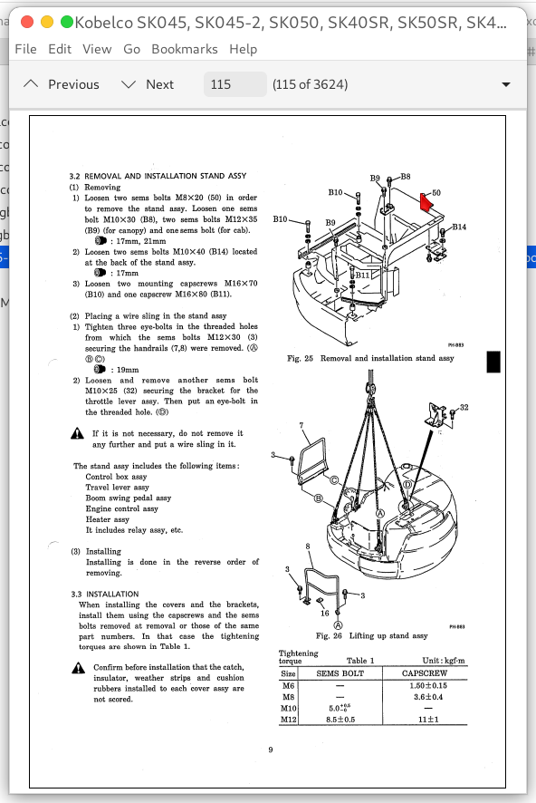
Complete digital official shop manual contains service, maintenance, and troubleshooting information for the Kobelco SK045, SK045-2, SK050, SK40SR, SK50SR, SK40SR-2, SK45SR-2 Hydraulic Excavators. Diagnostic and repair procedures are covered in great detail to repair, maintain, rebuild, refurbish or restore your vehicle like a professional mechanic in local service/repair workshop. This cost-effective quality manual is 100% complete and intact as should be without any missing pages. It is the same factory shop manual used by dealers that guaranteed to be fully functional to save your precious time.
This manual for Kobelco SK045, SK045-2, SK050, SK40SR, SK50SR, SK40SR-2, SK45SR-2 Hydraulic Excavators is divided into different sections. Each section covers a specific component or system and, in addition to the standard service procedures, includes disassembling, inspecting, and assembling instructions. A table of contents is placed at the beginning of each section. Pages are easily found by category, and each page is expandable for great detail. It is in the cross-platform PDF document format so that it works like a charm on all kinds of devices. You do not need to be skilled with a computer to use the manual.
3. REMOVAL AND INSTALLATION
3.1 GENERAL PRECAUTIONS
• Remove and install it in clean place.
• Before removing, clean the outside, particularly around the hydraulic oil port, and remove coating on the joints of each part with wire brush, etc.
• Wash and clean the removed parts with light oil.
• Put matchmark on the required parts to make the installation easier.
3.2 REMOVAL (REFER TO FIG. 2)
1) Fix the mounting flange (3) of the pump in a vise with the flange facing downward.
The aluminum plate, copper plate, etc. should be applied on the vice.
2) Loosen socket bolt (9), and remove it together with plain washer (10).
3) Remove the cover (1) straight up and off.
4) Remove the seal plate {7) and back-up (8).
5) Remove out the pressure plate (6).
6) Before removing, put matchmark on the end face of drive gear (4) and driven gear (5).
• Remove the drive gear (4) and driven gear (5).
7) Remove pressure plate (6).
• Remove it vertically in the shaft direction.
8) Identify the difference between the cover side and the flange side of the gear plate (2).
• The dowel pin on the gear plate (2) is press-fitted, so don’t remove it.
9) Remove seal plate (7) and back-up (8) from the mounting flange (3).
10) Turn over the mounting flange (3) and remove snap ring (12) and oil seal (11), too.
3.3 CHECK AND MAINTENANCE
Check the removed parts for possible damage and change in color and wash them with light oil. But rubber items must not be immersed in light oil.
Perform the following inspection, and replace the damaged parts with new ones.
1) Gear plate
The gear pump is designed in order to be operated under the condition where the tooth
tip contacts the body and is familiarized to achieve high volume efficiency. So the gear
pump operated once has contact trace to the suction part.
The allowable contact trace length is 1/2 or less than that of internal circumference of gear hole. And the allowable contact trace depth a is approx. 0.05mm. The depth a over 0.12mm is considered to be caused by the wear of shaft or bearing.
• The pump assy with a depth “a” of contact trace is 0.12mm or more should be replaced with a new one.
…
John Deere 886 Series Rear Mounted Row-Crop Cultivator Operator’s Manual (OMN200819)
“OMN200819 – John Deere 886 Series Rear Mounted Row-Crop Cultivator Operator’s Manual.pdf”
222 pages, bookmarked, Searchable, Printable, high quality PDF
Complete Operator’s Manuals for John Deere 886 Series Rear Mounted Row-Crop Cultivator. It’s the same service manual used by dealers that guaranteed to be fully functional and intact without any missing page.
This John Deere 886 Series Rear Mounted Row-Crop Cultivator Operator’s Manual is divided into different sections. Each section covers a specific component or system with detailed illustrations. A table of contents is placed at the beginning of each section. Pages are easily found by category, and each page is expandable for great detail. The printer-ready PDF documents work like a charm on all kinds of devices.
TABLE OF CONTENTS
Foreword
Section : 05 – Safety
Recognize Safety Information Understand Signal Words Follow Safety Instructions Operate Cultivator Safely
Park Cultivator Safely Keep Riders Off Machine Prepare for Emergencies Wear Protective Clothing Protect
Against Noise Handle Chemical Products Safely Handle Pesticides and Fertilizers Carefully Use Safety
Lights and Devices Transport Cultivator Safely Service Machine Safely Practice Safe Maintenance Remove
Paint Before Welding or Heating Avoid Heating Near Pressurized Fluid Lines Avoid High-Pressure Fluids
Check Hydraulic Hoses Support Raised Equipment Replacing Ground Engaging Tools Service Tires Safely
Safety Signs
Section : 10 – Preparing 4050/55, 4250/55, 4450/55 Tractors
Use Your Tractor Operator’s Manual Adjusting Tractor for Machine Hitch Conversion (4450/55 Tractors)
Lateral Float Adjust Rockshaft Selector Lever Adjusting Rate of Drop on Tractors Without Electronic Hitch
Section : 15 – Preparing 4555/60, 4755/60, 4955/60 Tractors
Adjusting Tractor for Machine Hitch Conversion Lateral Float For Tractors With Electronic
Hitch-Load/Depth Mix Control Adjusting Rate of Drop on Tractors With Electronic Hitch
Section : 20 – Preparing 7000 Series Tractors
Adjusting Tractor for Machine Hitch Conversion Lateral Float Load/Depth Mix Control-7000 Series Tractors
Adjust Rate of Drop on 7000 Series Tractors Prepare 7000 Series Tractor for Machine With Lift-Assist
Section : 25 – Preparing 8000 Series Tractors
Adjust Tractor for Machine Hitch Conversion Lateral Float Load/Depth Mix Control-8000 Series Tractors
Adjust Rate of Drop on 8000 Series Tractors
Section : 30 – Preparing the Machine
Setting Hitch Pins Determining Front Ballast Implement Codes-886 Row Crop Cultivator Lift-Assist
Installation Inflating Tires
Section : 35 – Attaching and Detaching
Attaching Machine to Tractor Setting Hitch Load Depth Control Using External Raise/Lower Switch
Rockshaft Control System Reset Attaching Machine to Tractor Without Quick-Coupler Attaching Machine to
Tractor With Quick-Coupler Attaching Warning Light Plug Attaching Wing Fold Hydraulic Hoses Attaching
Lift-Assist Hydraulic Hoses to 4050/55, 4250/55, and 4450/55 Tractors Attaching Lift-Assist Hydraulic
Hoses to 4555/60, 4755/60, and 4955/60 Tractors Attaching Machine With Lift-Assist to 4050/55, 4250/55,
4450/55 and 4555/60, 4755/60, 4955/60 Tractors Attaching Machine With Lift-Assist to 7000 Series Tractor
Attaching Machine With Lift-Assist to 8000 Series Tractor (For Single or Dual Lift Assist) DetachingMachine With Lift-Assist-4050/55, 4250/55 and 4450/55 Tractors Detaching Machine From Tractor
(4555/60, 4755/60, 4955/60) With Electronic Hitch with Lift-Assist Detaching Machine With Lift-Assist
From Tractor-7000 Series Detaching Machine With Lift-Assist From Tractor-8000 Series
Section : 40 – Transporting
Transport Procedure
Section : 45 – Operating the Machine
Guidelines for Use Tightening Hardware Control Levers Without Lift Assist Wheel (Attachment) Using Draft
Control-For Tractors With Electronic Hitch Control Levers for Machines with Lift Assist Wheel-Tractors
(4050/55, 4250/55, 4450/55) Without Electronic Hitch Control Levers for Machine With Lift-Assist
Wheel-Tractors (4555/60, 4755/60, 4955/60 and 7000) With Electronic Hitch Control Levers for Machine
With Lift-Assist Wheel-8000 Series Tractors Checking Lift-Assist Wheel (Single or Dual) Operation Leveling
Mainframe Leveling Wings Adjusting Rig Gauge Wheels Adjusting Coulters Changing Coulter Mounting
Position Adjusting Frame Gauge Wheels Setting Barring Off Disk Adjusting Rig Down-Pressure Springs
Adjusting Side Shields Adjusting Conventional Sweep Pitch Angle Adjusting Conservation Sweep Pitch
Angle Setting Conventional Adjustable Ridging Wings Adjusting Spring-Trip Shanks Wing Flotation
Operating Marker Arm (Attachment) Adjusting Marker Length Marker Breakaway Bolt Changing Row
Spacing
Section : 50 – Attachments
Conventional Ridging Wings Conservation Ridging Wings Plastic Covers for Conservation Ridging Wings
Rig Mounted Side and End Shields Implement Towing Hitch Anhydrous Knife Press Wheels Liquid Fertilizer
Tubes Spray Shields Dual Spray Attachment Hoses and Fittings Quick Attach Nozzles Model 4W With
914-1016 mm (36-40 in.) Hose and Fitting Layout Model 6N and 6W With 711-1016 mm (28-40 in.) Hose
and Fitting Layout Model 8N and 8W Rigid With 711-1016 mm (28-40 in.) Hose and Fitting Layout Model
8W Folding With 914-965 mm (36-38 in.) Hose and Fitting Layout Model 8W Folding With 1016 mm (40
in.) Hose and Fitting Layout Model 10N Folding With 762 mm (30 in.) Hose and Fitting Layout Model 10W
Folding With 914-965 mm (36-38 in.) Hose and Fitting Layout Model 12N Folding With 762 mm (30 in.)
Hose and Fitting Layout Model 12W Folding With 914-965 mm (36-38 in.) Hose and Fitting Layout Model
12W Folding With 1016 mm (40 in.) Hose and Fitting Layout Model 16N Folding With 762 mm (30 in.)
Hose and Fitting Layout Hydraulic Row Markers Shield Floatation Springs
Section : 55 – Lubrication and Maintenance
Lubricating and Maintaining Machine Safely Grease Alternative and Synthetic Lubricants Lubrication
Symbols Lubricate Rig Gauge Wheels-Every 25 Hours Lubricate Coulters-Every 25 Hours Lubricate
Down-Pressure Spring Adjustment-Every 250 Hours Lubricate Rig Gauge Wheel Adjustment-Every 250
Hours Lubricate Disk Hillers Angle Adjustment Spindle (A)-Every 250 Hours Lubricate Disk Hillers-Every
25 Hours Lubricate Frame Gauge Wheels-Every 250 Hours Lubricate Wing Hinges-Every 50 Hours Lubricate
Lift-Assist Wheel
Section : 60 – Troubleshooting
886 Rig 886 Rig With Fertilizer Knife Troubleshooting
Section : 65 – Service
Using Safe Service Procedures Practice Safe Maintenance Replacing Ground Engaging Tools Metric Bolt and
Cap Screw Torque Values Unified Inch Bolt and Cap Screw Torque Values Tightening Hardware Hitch and
Mast Brackets Rig Hanger Brackets Disk Hiller Clamps Adjusting Lift-Assist Wheel-Yoke Pivot Service
Tires Safely Removing Hydraulic Cylinders Installing and Bleeding Hydraulic Cylinders Attach Fold Link to
Wing Cylinders (50 Series Mainframe 178 x 178 mm, 7 x 7 in. Tube) Attach Fold Link to Wing Cylinders (80Series Mainframe 203 x 254 mm, 8 x 10 in.Tube) Sweeps Replacing Marker Breakaway Bolt Charging
Marker Hydraulic System Bleeding Marker Hydraulic System
Section : 70 – Storage
Preparing Cultivator for Storage Removing Cultivator From Storage
Section : 75 – Specifications
Implement-Tractor-Tire Compatibility Weights Product Identification Number Location
Section : 80 – Crime Prevention Tips
Help Prevent Crime Record AG Identification Numbers Keep Proof of Ownership Park Indoors Out of Sight
When Parking Outdoors Reduce Vandalism Report Thefts Immediately
Section : SLIT – John Deere Service Literature Available
Parts Catalog Operator’s Manual Technical and Service Manuals John Deere Publishing Books
Section : IBC – John Deere Service Keeps You On The Job
John Deere Is At Your Service When You Need It
…