Posted on

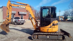
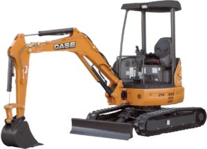
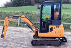
Case CX40B, CX50B Compact Hydraulic Excavator Workshop Repair & Service Manual


Download Link

INSTANT DOWNLOAD (add to cart)


Case CX40B, CX50B Compact Hydraulic Excavator Workshop Repair & Service Manual

total 3,779 pages, bookmarked, Searchable, Printable, high quality PDF

9-91930 – PELLE HYDRAULIQUE Case modèle CX40B, CX50B MANUEL DE SERVICE (FR).pdf
9-91940 – HYDRAULIC EXCAVATOR Case model CX40B, CX50B SHOP MANUAL (EN).pdf
9-91950 – HYDRAULIKBAGGER Case Modell CX40B, CX50B REPARATUR HANDBUCH (DE).pdf
9-91960 – EXCAVADORA HIDRÁULICA Case modelo CX40B, CX50B MANUAL DE REPARACIONES (ES).pdf
9-91970 – ESCAVATORE IDRAULICO Case modello CX40B, CX50B MANUALE ISTRUZIONI PER LE RIPARAZIONI (IT).pdf

Complete digital official shop manual contains service, maintenance, and troubleshooting information for the Case CX40B, CX50B Compact Hydraulic Excavator. Diagnostic and repair procedures are covered in great detail to repair, maintain, rebuild, refurbish or restore your Case CX40B, CX50B like a professional mechanic in local service/repair workshop. This cost-effective quality manual is 100% complete and intact as should be without any missing pages. It is the same factory shop manual used by dealers that guaranteed to be fully functional to save your precious time.

This manual for Case CX40B, CX50B is divided into different sections. Each section covers a specific component or system and, in addition to the standard service procedures, includes disassembling, inspecting, and assembling instructions. A table of contents is placed at the beginning of each section. Pages are easily found by category, and each page is expandable for great detail. It is in the cross-platform PDF document format so that it works like a charm on all kinds of devices. You do not need to be skilled with a computer to use the manual.

EXCERPT:
INDEX
1 SPECIFICATIONS
2 MAINTENANCE
3 SYSTEM
4 DISASSEMBLING
5 TROUBLESHOOTING
6 ENGINE
7 INSTALLATION PROCEDURES FOR OPTIONAL ATTACHMENT
8 SUPPORTING DATA

Posted on

Case CX31B, CX36B Compact Hydraulic Excavator Workshop Repair & Service Manual


Download Link

INSTANT DOWNLOAD (add to cart)


total 4,979 pages, bookmarked, Searchable, Printable, high quality PDF

9-91731 – PELLE HYDRAULIQUE Case modèle CX31B, CX36B MANUEL DE SERVICE (FR).pdf
9-91741 – HYDRAULIC EXCAVATOR Case model CX31B, CX36B SHOP MANUAL (EN).pdf
9-91751 – HYDRAULIKBAGGER Case Modell CX31B, CX36B REPARATUR HANDBUCH (DE).pdf
9-91761 – EXCAVADORA HIDRÁULICA Case modelo CX36B, CX31B MANUAL DE REPARACIONES (ES).pdf
9-91771 – ESCAVATORE IDRAULICO Case modello CX31B, CX36B MANUALE ISTRUZIONI PER LE RIPARAZIONI (IT).pdf
87722071 NA – CX36B Tier 4 Compact Crawler Excavator Operator’s Manual.pdf – 180 pages
S5PW0032E02 – CX31B, CX36B Compact Hydraulic Excavator Service Manual.pdf – 949 pages, English, August 2010

Complete digital official shop manual contains service, maintenance, and troubleshooting information for the Case CX31B, CX36B Compact Hydraulic Excavator. Diagnostic and repair procedures are covered in great detail to repair, maintain, rebuild, refurbish or restore your Case CX31B, CX36B like a professional mechanic in local service/repair workshop. This cost-effective quality manual is 100% complete and intact as should be without any missing pages. It is the same factory shop manual used by dealers that guaranteed to be fully functional to save your precious time.

This manual for Case CX31B, CX36B is divided into different sections. Each section covers a specific component or system and, in addition to the standard service procedures, includes disassembling, inspecting, and assembling instructions. A table of contents is placed at the beginning of each section. Pages are easily found by category, and each page is expandable for great detail. It is in the cross-platform PDF document format so that it works like a charm on all kinds of devices. You do not need to be skilled with a computer to use the manual.
EXCERPT:
24. COMPONENTS SYSTEM
24.1.2.3 OPERATION
(1) Lever in neutral position
In this case, the force of the secondary pressure setting spring (241) that determines the output pressure of the pilot valve is not transmitted to the spool (201). Accordingly, the spool (201) is pushed up by the return spring (221) and spring seat (216) permitting the output port 2, 4 to connect with the tank port T. This makes the output pressure equal to the tank pressure.
Lever in neutral position
(2) When the Lever is tilted
When the lever is tilted, the push rod (212) strokes. The spool (201) and spring seat (216) moves downward to make the port P to connect with the port 2, 4. With the result that the oil of the pilot pump flow out to the port 2, 4, to produce a pressure.
When Lever is tilted
(3) The Lever being held
When the lever is tilted till the pressure of the port 2, 4 rises to an oil pressure corresponding to the set spring force, the hydraulic pressure is balanced with the spring (241) force. And when the pressure of the port 2, 4 rises above a set pressure, the port P are closed and the port T are opened. When the pressure of the port 2, 4 falls below a set pressure, the port P are caused to open and the port T are caused to close, thus holding the second pressure constant.

33. UPPER SLEWING STRUCTURE
(4)Remove dust seal (10) from the shaft.
(5)Remove seal, etc. from the inside of the body.
-Be sure of the position of seal, etc. referring to the construction drawing.
-Take out O-ring with the pointed tool like a gimlet.
(1) Insert seals in the body.
-Check the seal position referring to the construction drawing.
-Ensure that O-rings are free from twisting.
-Don’t deform or bend the slipper seal extremely.
(2) Install dust seal (10) to shaft (1).
-Apply enough grease to the lip section of the dust seal.
(3) Install shaft (1) to body (2).
-Apply hydraulic oil or grease around the shaft lightly.
-Strike the shaft with a plastic hammer carefully not to damage seal.
(4) Fit thrust ring (4) and snap ring (11).
-Fit the snap ring in the groove correctly.
(5) Fit O-ring (8) and install flange (3).
(6) Install spring washer (14) and bolt (12).
Tools: Socket: 17 mm
or
Tools: Spanner: 17 mm
-Tightening torque : 52 to 57 N-m (38 to 42 lbf-ft)
-Put pipe through the locking pin of the shaft, and check that the shaft rotates smoothly at a torque of approximately 78 to 108 N-m (58 to 80 lbf-ft)
33.2.6.3 MAINTENANCE STANDARDS
33.2.6.3.1 Check Procedures and Remedy

Posted on

CNH Excavators CX20B, CX22B, CX27B Workshop Repair & Service Manual


Download Link

INSTANT DOWNLOAD (add to cart)


3,500+ total pages, bookmarked, Searchable, Printable, high quality PDF

9-91831 – Case PELLE HYDRAULIQUE modèle CX20B, CX22B, CX27B MANUEL DE SERVICE (FR).pdf
9-91841 – Case HYDRAULIC EXCAVATOR model CX20B, CX22B, CX27B SHOP MANUAL (EN).pdf
9-91851 – Case HYDRAULIKBAGGER Modell CX20B, CX22B, CX27B REPARATUR HANDBUCH (DE).pdf
9-91861 – Case EXCAVADORA HIDRÁULICA modelo CX20B, CX22B, CX27B MANUAL DE REPARACIONES (ES).pdf
9-91871 – Case ESCAVATORE IDRAULICO modello CX20B, CX22B, CX27B MANUALE ISTRUZIONI PER LE RIPARAZIONI (IT).pdf

Complete digital official shop manual contains service, maintenance, and troubleshooting information for the CNH Excavators CX20B, CX22B, CX27B. Diagnostic and repair procedures are covered in great detail to repair, maintain, rebuild, refurbish or restore your CNH Excavators CX20B, CX22B, CX27B like a professional mechanic in local service/repair workshop. This cost-effective quality manual is 100% complete and intact as should be without any missing pages. It is the same factory shop manual used by dealers that guaranteed to be fully functional to save your precious time.

EXCERPT:
(1) Engage the rubber crawler with the sprocket and mount it on the idler.
(2) Put steel pipes (P) in the rubber crawler, turn the sprocket in the reverse direction slowly and then the rubber crawler has floated off the idler, stop the rotating.
(3) Slide the rubber crawler to the position to be set on idler exactly.
Fig. 34-5 Installing rubber crawler
(4) Confirm that the rubber crawler is engaged securely with the sprocket, idler and lower roller.
(5) Tighten the grease nipple for the crawler adjuster, and adjust tension by feeding grease.

Posted on

CNH Mini Excavators CX16B and CX18B Workshop Repair & Service Manual


Download Link

INSTANT DOWNLOAD (add to cart)


CNH Mini Excavators CX16B and CX18B Workshop Repair & Service Manual

3,000+ total pages, bookmarked, Searchable, Printable, high quality PDF

9-88660 – CNH Mini Pelles CX16B et CX18B MANUEL DE SERVICE (FR).pdf
9-88670 – CNH Mini Excavators CX16B and CX18B SERVICE MANUAL (EN).pdf
9-88680 – CNH Minibaggers CX16B und CX18B WERKSTATTHANDBUCH (DE).pdf
9-88690 – CNH Mini Excavadoras CX16B y CX18B MANUAL DE INSTRUCCIONES PARA LA REPARACION (ES).pdf
9-88700 – CNH Mini Escavatori CX16B e CX18B MANUALE PER LE RIPARAZIONI (IT).pdf

Complete digital official shop manual contains service, maintenance, and troubleshooting information for the CNH Mini Excavators CX16B and CX18B. Diagnostic and repair procedures are covered in great detail to repair, maintain, rebuild, refurbish or restore your CNH Mini Excavators CX16B and CX18B like a professional mechanic in local service/repair workshop. This cost-effective quality manual is 100% complete and intact as should be without any missing pages. It is the same factory shop manual used by dealers that guaranteed to be fully functional to save your precious time.

EXCERPT:
When aligning the pin borees, do not put your finger in the pin holes in any circumstances, but align them visually.
• Clean the welded part of the structures and check that there is no crack on the part.
• Check that the dust seal is not damaged, and replace a faulty one if necessary.
• When inserting the pin, coat the shaft with grease.
– The bucket can be mounted easily if the bucket link is installed in the beginning.

Posted on

CNH Hydraulic hammers CB Series Workshop Repair & Service Manual


Download Link

INSTANT DOWNLOAD (add to cart)


500+ total pages, bookmarked, Searchable, Printable, high quality PDF

603.67.220.00 – CNH Martelli idraulici Serie CB Service Manual (IT).pdf
603.67.221.00 – CNH Hydraulic hammers CB Serie Service Manual (EN).pdf
603.67.222.00 – CNH Marteaux hydrauliques Serie CB Service Manuel (FR).pdf
603.67.223.00 – CNH Martillos hidráulicos Serie CB Service Manual (ES).pdf
603.67.224.00 – CNH Hydraulikhämmer Serien CB Service Manual (DE).pdf

Complete digital official shop manual contains service, maintenance, and troubleshooting information for the CNH Hydraulic hammers CB Series (CB32, CB45, CB65, CB85, CB120, CB150, CB200S, CB260S, CB320S, CB400S, CB550S, CB700S). Diagnostic and repair procedures are covered in great detail to repair, maintain, rebuild, refurbish or restore your Case CB200 S – CB260 S – CB320 S – CB400 S – CB550 S – CB700 S like a professional mechanic in local service/repair workshop. This cost-effective quality manual is 100% complete and intact as should be without any missing pages. It is the same factory shop manual used by dealers that guaranteed to be fully functional to save your precious time.

This manual for CNH Hydraulic hammers CB Series is divided into different sections. Each section covers a specific component or system and, in addition to the standard service procedures, includes disassembling, inspecting, and assembling instructions. A table of contents is placed at the beginning of each section. Pages are easily found by category, and each page is expandable for great detail. It is in the cross-platform PDF document format so that it works like a charm on all kinds of devices. You do not need to be skilled with a computer to use the manual.

EXCERPT:
Hydraulic hammers CB32 – CB45 – CB65 – CB85 – CB120 – CB150 ….7-22011GB
Hydraulic hammers CB200 S – CB260 S – CB320 S – CB400 S – CB550 S – CB700 S… 7-23861GB

TABLE OF CONTENTS
TECHNICAL SPECIFICATIONS …3
Overall dimensions….3
SPECIFICATIONS…9
TORQUE SETTINGS ….10
TOOLS REQUIRED ….10
SPECIAL TOOLS ….11
REPLACING A HYDRAULIC HAMMER….12
HANDLING THE HYDRAULIC HAMMER …14
IHYDRAULIC BREAKER OVERALL DIMENSIONS …16
HAMMER HYDRAULIC PRESSURE DISCHARGE….17
LOCATION OF MAIN COMPONENTS …18
CB32 – CB45 – CB65 – CB85 – CB120 – CB150 ….18
Removing the chassis plates ….19
Installing the chassis plates ….20
Releasing pressure in the low pressure accumulator….21
LOW PRESSURE ACCUMULATOR…21
Releasing pressure from the high pressure accumulator….24
HIGH PRESSURE ACCUMULATOR ….24
CHARGING THE ACCUMULATOR ….27
Charging….27
PRESSURE REGULATING VALVE….29
Assembly…30
TIE-RODS …32
Removal ….32
CONTROL VALVE COMPONENTS (CB32 – CB85) …35
Removal ….35
CONTROL VALVE BODY COMPONENTS (CB45 – CB65 – CB120 – CB150) …38
Removal ….38
CYLINDER ….42
Removal ….42
FRONT PART….45
Removal ….45
CHANGING A TOOL …48
Removal ….48
Installation …49
Cre 7-22011GB
Issued 01- 052
CHANGING THE TOOL BUSHING…50
Removal ….50
Installation …50
WEAR LIMITS …51
Tool bushings….51
Tools …51
INSPECTION AND MEASUREMENT OF HYDRAULIC HAMMER CIRCUIT…52
Measurement/inspection points ….52
MEASURING THE HYDRAULIC HAMMER OPERATING PRESSURE…54
OPERATING PRINCIPLES …56
TROUBLESHOOTING ….59

Procedure for taking measurements
Procedure for measurement and adjustment of hydraulic hammer:
NOTE: Inspect and calibrate all the gauges: pressure gauges which are to be used. Change any defective pressure gauge.
NOTE: If the flow towards the hydraulic hammer is set by changing the speed of the engine, the flow should always be checked with the engine at maximum speed.
NOTE: It is strictly forbidden to operate the hydraulic hammer at a flow higher than the specifications.