Posted on

New Holland CR9060 Elevation, CR9060, CR9070 Elevation, CR9080 Elevation, CR9080, CR9090 Elevation, CX8030, CX8040, CX8050, CX8060, CX8070, CX8080, CX8090 Combine Harvesters Factory Service & Shop Manual


New_Holland_CR9060_CR9070_CR9080_CR9090_CX8030_CX8040_CX8050_CX8060_CX8070_CX8080_CX8090


INSTANT DOWNLOAD


Complete workshop & service manual with electrical wiring diagrams for New Holland CR9060 Elevation, CR9060, CR9070 Elevation, CR9080 Elevation, CR9080, CR9090 Elevation, CX8030, CX8040, CX8050, CX8060, CX8070, CX8080, CX8090 Combine Harvesters. It’s the same service manual used by dealers that guaranteed to be fully functional and intact without any missing page.

This New Holland CR9060 Elevation, CR9060, CR9070 Elevation, CR9080 Elevation, CR9080, CR9090 Elevation, CX8030, CX8040, CX8050, CX8060, CX8070, CX8080, CX8090 Combine Harvesters service & repair manual (including maintenance, overhaul, disassembling & assembling, adjustment, tune-up, operation, inspecting, diagnostic & troubleshooting…) is divided into different sections. Each section covers a specific component or system with detailed illustrations. A table of contents is placed at the beginning of each section. Pages are easily found by category, and each page is expandable for great detail. The printer-ready PDF documents work like a charm on all kinds of devices.

87725889C – CR9060 Elevation, CR9060, CR9070 Elevation, CR9080 Elevation, CR9080, CR9090 Elevation, CX8030, CX8040, CX8050, CX8060, CX8070, CX8080, CX8090 Service Manual.pdf – 3,528 pages

EXCERPT:
Contents
INTRODUCTION
DISTRIBUTION SYSTEMS….. A
PRIMARY HYDRAULIC POWER SYSTEM . . . . . . . A.10.A
SECONDARY HYDRAULIC POWER SYSTEM. . . . . A.12.A
HYDRAULIC COMMAND SYSTEM. . . . . . . A.14.A
PNEUMATIC SYSTEM . . . . . . . . . A.20.A
ELECTRICAL POWER SYSTEM . . . . . . . A.30.A
LIGHTING SYSTEM. . . . . . . . . . A.40.A
ELECTRONIC SYSTEM . . . . . . . . . A.50.A
FAULT CODES . . . . . . . . . A.50.A
POWER PRODUCTION ……… B
ENGINE . . . . . . . . . . B.10.A
FUEL AND INJECTION SYSTEM. . . . . . . B.20.A
AIR INTAKE SYSTEM . . . . . . . . . . B.30.A
EXHAUST SYSTEM. . . . . . . . . . B.40.A
ENGINE COOLANT SYSTEM . . . . . . . . B.50.A
ENGINE CLEANING SYSTEM Blow off system . . . . B.62.B
STARTING SYSTEM . . . . . . . . . B.80.A
POWER TRAIN …..C
POWER COUPLING Fixed coupling . . . . . . . . C.10.B
TRANSMISSION Mechanical . . . . . . . C.20.B
TRANSMISSION Hydrostatic. . . . . . . . C.20.F
PROCESS DRIVE Primary process drive . . . . . . . C.50.B
TRAVELLING……..D
FRONT AXLE . . . . . . . . . . D.10.A
REAR AXLE . . . . . . . . . . D.12.A
2WD-4WD SYSTEM Hydrostatic . . . . . . . . D.14.E
STEERING Hydraulic. . . . . . . . . . D.20.C
STEERING AutoPilot . . . . . . . . . D.20.E
SERVICE BRAKE Hydraulic. . . . . . . . D.30.C
PARKING BRAKE Hydraulic . . . . . . . D.32.C
BODY AND STRUCTURE …… E
SHIELD . . . . . . . . E.20.A
OPERATOR AND SERVICE PLATFORM . . . . . . . E.30.A
USER CONTROLS AND SEAT . . . . . . . E.32.A
USER CONTROLS AND SEAT Operator seat . . . . . . E.32.C
USER PLATFORM . . . . . . . . . E.34.A
ENVIRONMENT CONTROL Heating system . . . . . . . E.40.B
ENVIRONMENT CONTROL Air-conditioning system . . . . . . E.40.C
ENVIRONMENT CONTROL Heating, ventilation and air-conditioning. . . . E.40.D
SAFETY SECURITY ACCESSORIES Safety . . . . . . . E.50.B
TOOL POSITIONING …. G
LIFTING . . . . . . . . . G.10.A
LEVELLING . . . . . . . . . G.30.A
CROP PROCESSING …. K
FEEDING Header feeding. . . . . . . . K.25.D
FEEDING Feeder housing . . . . . . . K.25.E
FEEDING Rotor feeding. . . . . . . . . . K.25.N
THRESHING Conventional threshing . . . . . . . K.40.B
THRESHING Twin flow threshing . . . . . . . K.40.D
SEPARATING Beating. . . . . . . . . . K.42.B
SEPARATING Rotary separator . . . . . . . K.42.C
SEPARATING Twin flow rotor . . . . . . . K.42.D
SEPARATING Straw walker . . . . . . K.42.E
SEPARATING Straw flow beater . . . . . . . . K.42.F
SEPARATING Discharge beater . . . . . . . K.42.G
STORING AND HANDLING Grain storing . . . . . . . . K.60.B
CLEANING Primary cleaning. . . . . . . . K.62.B
CLEANING Tailings return system . . . . . . . . K.62.C
RESIDUE HANDLING Straw chopper. . . . . . K.64.C
RESIDUE HANDLING Spreader . . . . . . . . K.64.D
RESIDUE HANDLING Chaff blower. . . . . . . K.64.F
RESIDUE HANDLING Chaff spreader . . . . . . . K.64.G
RESIDUE HANDLING Positive straw discharge (PSD) . . . . . . K.64.H
UNLOADING Grain unloading. . . . . . . K.72.B
PROTECTION SYSTEMS Reversing system . . . . . . . K.90.C
PROTECTION SYSTEMS Stone trapping . . . . . . . . K.90.E

INSTANT DOWNLOAD


Posted on

JCB Side Engine Loadalls (526, 531, 533, 535, 536-60, 540, 541) Factory Service & Shop Manual


Pages from 9803-3760 – JCB Side Engine Loadalls (526-56, 531-70, 531-T70, 533-105, 535-95, 535-T95, 536-60, 536-T60, 536-70, 536-T70, 541-70, 541-T70) Service Manual

MJCB526LOA541OPES.zip
Price: $29.99 USD

Complete workshop & service manual with electrical wiring diagrams for JCB Side Engine Loadalls (526-56, 531-70, 531-T70, 533-105, 535-95, 535-T95, 535-125, 535-125 HiViz, 535-140 HiViz, 536-60, 536-T60, 536-70, 536-T70, 540-140, 540-170, 541-70, 541-T70). It’s the same service manual used by dealers that guaranteed to be fully functional and intact without any missing page.

This JCB Side Engine Loadalls (526-56, 531-70, 531-T70, 533-105, 535-95, 535-T95, 535-125, 535-125 HiViz, 535-140 HiViz, 536-60, 536-T60, 536-70, 536-T70, 540-140, 540-170, 541-70, 541-T70) service & repair manual (including maintenance, overhaul, disassembling & assembling, adjustment, tune-up, operation, inspecting, diagnostic & troubleshooting…) is divided into different sections. Each section covers a specific component or system with detailed illustrations. A table of contents is placed at the beginning of each section. Pages are easily found by category, and each page is expandable for great detail. The printer-ready PDF documents work like a charm on all kinds of devices.

FILELIST:
9803-3730 – JCB Side Engine Loadalls (526-56, 531-70, 533-105, 535-95, 535-125, 535-125 HiViz, 535-140 HiViz, 536-60, 536-70, 540-140, 540-170, 541-70) Service Manual.pdf
9803-3760 – JCB Side Engine Loadalls (526-56, 531-70, 531-T70, 533-105, 535-95, 535-T95, 536-60, 536-T60, 536-70, 536-T70, 541-70, 541-T70) Service Manual.pdf

EXCERPT:
Service Manual
Side Engine Loadalls
Section 1 – General Information
Section 2 – Care and Safety
Section 3 – Routine Maintenance
Section B – Body and Framework
Section C – Electrics
Section E – Hydraulics
Section F – Transmission
Section G – Brakes
Section H – Steering
Section K – Engine
Section M – Electronic Data Systems

Main System Pressures
To investigate any hydraulic performance issues you must complete the pressure tests.
– Stand-by Pressure – This is the pressure measured at the pump when the hydraulic services are not operated.
– Delta P Pressure – This is the pressure setting of the pump controller. The controller makes sure that the pump delivers a pressure above what is required by
the hydraulic services. This extra pressure is the delta P pressure.
– Load Sense Relief Valve Pressure – This is the maximum pressure that can be achieved within the hydraulic system.
Note: This procedure describes the correct method to check the main system pressure, load sense pressure, pump standby pressure, steering pressure and delta-P
pressure. A multi-channel digital pressure test set will be required to measure the pressures accurately (see Service Tools).

Posted on

JCB 500 Series Loadalls Factory Service & Shop Manual


Pages from 9803-3600 – JCB 500 Series (525-58, 525-67, 530-67, 530-95, 530-110, 530-120, 535-67, 537-120, 537-130) Service Manual

MJCB525LOA537OPES.zip
Price: $29.99 USD

Complete workshop & service manual with electrical wiring diagrams for JCB 500 Series (525-58, 525-67, 530-67, 530-95, 530-110, 530-120, 532H, 535-67, 537-120, 537-130, 537H). It’s the same service manual used by dealers that guaranteed to be fully functional and intact without any missing page.

This JCB 500 Series (525-58, 525-67, 530-67, 530-95, 530-110, 530-120, 532H, 535-67, 537-120, 537-130, 537H) service & repair manual (including maintenance, overhaul, disassembling & assembling, adjustment, tune-up, operation, inspecting, diagnostic & troubleshooting…) is divided into different sections. Each section covers a specific component or system with detailed illustrations. A table of contents is placed at the beginning of each section. Pages are easily found by category, and each page is expandable for great detail. The printer-ready PDF documents work like a charm on all kinds of devices.

9803-3600 – JCB 500 Series (525-58, 525-67, 530-67, 530-95, 530-110, 530-120, 535-67, 537-120, 537-130) Service Manual.pdf
9803-3641 – JCB 532H, 537H Service Manual Supplement to 9803-3600.pdf

This Service Manual covers the following Machines:-
525-58 and 525-58 Farm Special – from machine Serial Number 561001
525-67 and 525-67 Farm Special – from machine Serial Number 561001
525-58 and 525-67 Farm Special Plus
525-58 and 525-67 Basic Servo Options
527-58 and 527-67 – from machine Serial Number 572775
530-95 – from machine Serial Number 564980
530-110 – from machine Serial Number 563359
530-110 and 530-120 – PlaceAce
530-110 and 530-120 Servo Options
530-120 – from machine Serial Number 562601
530-67 and 530-67 Farm Special – from machine Serial Number 571001
535-67 – from machine Serial Number 572775
537-120 and 537-130 from machine Serial Number 572900
Information covers two stage and three stage boom machines.

EXCERPT:
General 1
Hydraulics 2
Body and Framework 3
PlaceAce Control System 4
Servo Control System 4A
Engine 5
Transmission 6
Axles 7
Brakes 8
Hydraulic Steering 9
Electrics 10
Service Tools 11
Index

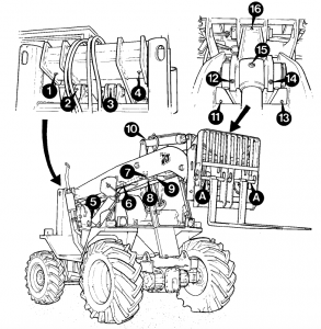
REAR HUB (Splined), BRAKES AND DRIVESHAFTASSEMBLY.
1 Install the drive shaft inner bearing assembly (see page 7/ 5-5 Step 1 and Step 2).
2 Fit drive shaft inner end into splines of differential gears (see page 7/5-5 Step 3).
3 Fit needle roller bearing 1 and seal 2 into hub swivel 3.
Note: Do not force fit bearing 1 and make sure the manufacturers mark is facing out.
4 Assemble top and bottom trunnions (see page 7/5-5 Step 4 and 7/5-8 Step 6 to 9).
5 Lightly oil the inner wheel bearing race 6. Assemble the bearing cup 7 and bearing race into the bearing carrier 8.
6 Fit a new type combination seal 9 into the bearing carrier 8 so that the chamfer faces the hub swivel. Do not disassemble seal or use excessive force when fitting.
Note: Make sure the seal enters squarely and that the surface of the seal is 5 mm (0.2 in) A from the end of the bore of the bearing carrier, as shown.
7 Lightly oil the inner wheel bearing race 11. Assemble the bearing cup 10 and bearing race into the bearing carrier 8. Fit bearing carrier onto axle stub.

Posted on

JCB Loadall Range (520, 520HL, 520 Farm Special, 520M, 525, 525B, 525BHL, 525B Farm Special, 530, 530HL, 530B, 530BHL, 540B, 540BM) Factory Service & Shop Manual


Pages from 9803-3350 – JCB Loadall Range (520, 520HL, 520 Farm Special, 520M, 525, 525B, 525BHL, 525B Farm Special, 530, 530HL, 530B, 530BHL, 540B, 540BM) Service Manual

MJCB520LOA540OPES.zip
Price: $29.99 USD

Complete workshop & service manual with electrical wiring diagrams for JCB Loadall Range (520, 520HL, 520 Farm Special, 520M, 525, 525B, 525BHL, 525B Farm Special, 530, 530HL, 530B, 530BHL, 540B, 540BM). It’s the same service manual used by dealers that guaranteed to be fully functional and intact without any missing page.

This JCB Loadall Range (520, 520HL, 520 Farm Special, 520M, 525, 525B, 525BHL, 525B Farm Special, 530, 530HL, 530B, 530BHL, 540B, 540BM) service & repair manual (including maintenance, overhaul, disassembling & assembling, adjustment, tune-up, operation, inspecting, diagnostic & troubleshooting…) is divided into different sections. Each section covers a specific component or system with detailed illustrations. A table of contents is placed at the beginning of each section. Pages are easily found by category, and each page is expandable for great detail. The printer-ready PDF documents work like a charm on all kinds of devices.

9803-3350 – JCB Loadall Range (520, 520HL, 520 Farm Special, 520M, 525, 525B, 525BHL, 525B Farm Special, 530, 530HL, 530B, 530BHL, 540B, 540BM) Service Manual.pdf
9803-3352 – JCB Loadall Range Servo Hydraulics (525B-HL, 530B-HL) Service Manual Supplement.pdf

EXCERPT:
Transmission 6
GEARBOX
SELECTORS
Dismantling and Assembly
When Dismantling 7′ When removing selector fork 3 from rail, care to be taken not to 1 loose ball 4 and spring 5.

Posted on

JCB Loadall 520-40, 520-50, 524-50, 525-50, 525-50S, 520-55 RS/AWS, 526-55, 526-55 AWS, 526S AWS, 527-55 Factory Service & Shop Manual


Pages from 9803-3690 – JCB Compact Loadalls (520-40, 524-50, 527-55) Service Manual

MJCB520LOA527OPES.zip
Price: $29.99 USD

Complete workshop & service manual with electrical wiring diagrams for JCB Loadall (520-40, 520-50, 524-50, 525-50, 525-50S, 520-55 RS, 520-55 AWS, 526-55, 526-55 AWS, 526S AWS, 527-55). It’s the same service manual used by dealers that guaranteed to be fully functional and intact without any missing page.

This JCB Loadall (520-40, 520-50, 524-50, 525-50, 525-50S, 520-55 RS, 520-55 AWS, 526-55, 526-55 AWS, 526S AWS, 527-55) service & repair manual (including maintenance, overhaul, disassembling & assembling, adjustment, tune-up, operation, inspecting, diagnostic & troubleshooting…) is divided into different sections. Each section covers a specific component or system with detailed illustrations. A table of contents is placed at the beginning of each section. Pages are easily found by category, and each page is expandable for great detail. The printer-ready PDF documents work like a charm on all kinds of devices.

FILELIST:
9803-3610 – JCB Loadall (520-55 RS/AWS, 526-55, 526-55 AWS, 526S AWS) Service Manual.pdf
9803-3620 – JCB Loadall (520-50, 525-50, 525-50S) Service Manual.pdf
9803-3690 – JCB Compact Loadalls (520-40, 524-50, 527-55) Service Manual .pdf
Loadalls 2000_2010 Electrical Wiring Diagrams (BONUS MATERIAL).pdf

EXCERPT:
Service Manual
Compact Loadalls
Section 1 – General Information
Section 2 – Care and Safety
Section 3 – Maintenance
Section A – Attachments
Section B – Body and Framework
Section C – Electrics
Section D – Controls
Section E – Hydraulics
Section F – Transmissions
Section G – Brakes
Section H – Steering
Section K – Engine

Fire Extinguisher (if fitted)
Checking the Fire Extinguisher
Check the fire extinguisher for damage, security and signs of leaking.
Check that the gauge A indicates that the extinguisher is charged i.e. the needle is in the GREEN segment.
Note: If the needle is in or very near the RED segment at either end of the gauge, the extinguisher must be serviced or replaced.
Make sure the safety pin B is fitted and secure.
The extinguisher should be serviced every 12 months by a suitably qualified person.