Posted on

Case Wheel Loader 821G, 921G Factory Service & Shop Manual


Download Link

INSTANT DOWNLOAD (add to cart)


total 2,707 pages, bookmarked, Searchable, Printable, high quality PDF
48082199 – Wheel Loader 821G, 921G Stage IV Service Manual.pdf; 2,707 pages
SERVICE MANUAL
821G WHEEL LOADER XR-EH, NEW CAB TIER4B
821G WHEEL LOADER ZBAR-EH, NEW CAB TIER4B
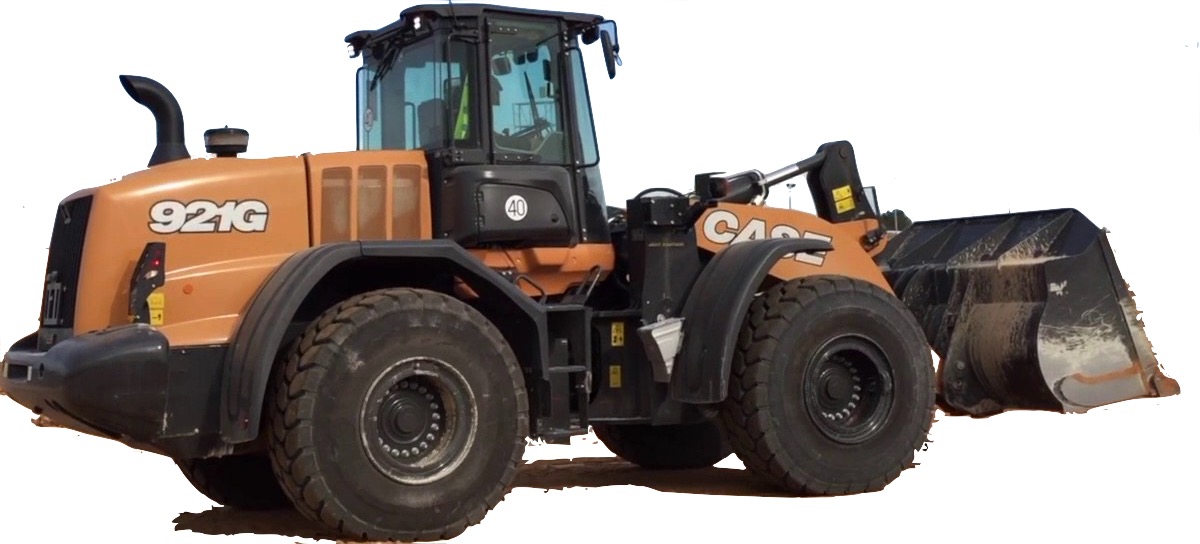
921G WHEEL LOADER XR-EH, NEW CAB TIER4B
921G WHEEL LOADER ZBAR-EH, NEW CAB TIER4B

Complete workshop & service manual with electrical wiring diagrams for Case Wheel Loader 821G, 921G. It’s the same service manual used by dealers that guaranteed to be fully functional and intact without any missing page.

This Case Wheel Loader 821G, 921G service & repair manual (including maintenance, overhaul, disassembling & assembling, adjustment, tune-up, operation, inspecting, diagnostic & troubleshooting…) is divided into different sections. Each section covers a specific component or system with detailed illustrations. A table of contents is placed at the beginning of each section. Pages are easily found by category, and each page is expandable for great detail. The printer-ready PDF documents work like a charm on all kinds of devices.

EXCERPT:
Contents
INTRODUCTION
Engine.. 10
[10.001] Engine and crankcase . . 10.1
[10.202] Air cleaners and lines . . 10.2
[10.500] Selective Catalytic Reduction (SCR) exhaust treatment . . 10.3
[10.400] Engine cooling system . . 10.4
[10.414] Fan and drive . . 10.5
[10.310] Aftercooler. . 10.6
[10.304] Engine lubrication system . . 10.7
Transmission.. 21
[21.113] Powershift transmission . . 21.1
[21.155] Powershift transmission internal components. . 21.2
[21.700] Torque converter . . 21.3
Four-Wheel Drive (4WD) system .. 23
[23.314] Drive shaft. . 23.1
Front axle system .. 25
[25.100] Powered front axle . . 25.1
[25.102] Front bevel gear set and differential . . 25.2
[25.108] Final drive hub, steering knuckles, and shafts . . 25.3
Rear axle system.. 27
[27.100] Powered rear axle. . 27.1
[27.106] Rear bevel gear set and differential . . 27.2
[27.120] Planetary and final drives . . 27.3
Brakes and controls .. 33
[33.202] Hydraulic service brakes . . 33.1
[33.110] Parking brake or parking lock . . 33.2
Hydraulic systems.. 35
[35.000] Hydraulic systems. . 35.1
[35.300] Reservoir, cooler, and filters. . 35.2
[35.106] Variable displacement pump . . 35.3
[35.359] Main control valve . . 35.4
[35.357] Pilot system . . 35.5
[35.752] Hydraulic fan drive cooling system. . 35.6
[35.701] Front loader arm hydraulic system . . 35.7
[35.723] Front loader bucket hydraulic system . . 35.8
[35.734] Tool quick coupler hydraulic system . . 35.9
Frames and ballasting .. 39
[39.100] Frame . . 39.1
Steering.. 41
[41.101] Steering control . . 41.1
[41.200] Hydraulic control components. . 41.2
[41.216] Cylinders . . 41.3
[41.910] Auxiliary steering . . 41.4
Wheels.. 44
[44.511] Front wheels. . 44.1
[44.520] Rear wheels . . 44.2
Cab climate control .. 50
[50.200] Air conditioning. . 50.1
Electrical systems .. 55
[55.100] Harnesses and connectors. . 55.1
[55.301] Alternator. . 55.2
[55.302] Battery. . 55.3
[55.988] Selective Catalytic Reduction (SCR) electrical system . . 55.4
[55.989] Exhaust Gas Recirculation (EGR) electrical system . . 55.5
[55.512] Cab controls. . 55.6
[55.530] Camera. . 55.7
[55.DTC] FAULT CODES. . 55.8
Front loader and bucket.. 82
[82.100] Arm. . 82.1
[82.300] Bucket . . 82.2
Platform, cab, bodywork, and decals .. 90
[90.150] Cab. . 90.1
[90.105] Machine shields and guards . . 90.2
..
Rear axle system – Planetary and final drives
Wheel hub – Visual inspection – Models MT-L 3085 II / MT-L 3095 II
1. Clean all parts except the friction plates in the brake disc pack by using cleaning solvent. Use compressed air to clear the passages in the planetary ring gear and brake housing.
NOTICE: wear face protection when using compresses air.
2. Inspect the bearing rollers for pitting, scoring, deformation, or other damage. Check the inner face and bearing cage for deformation, dents, and other damage.
Check the associated bearing cups for scratches, grooves, or cracks. Check the bearings for rough spots or binding by holding bearing and rotating. If the bearing binds or action is not smooth, replace the bearing.
3. Inspect the bearing cups for pitting, scoring, cracks, or other damage. Replace if any of these conditions are seen.
NOTE: if a bearing or bearing cup requires replacement, the associated part must also be replaced.
4. Check the planetary ring gear, planetary gears, and planetary carrier gear teeth for cracks, breaks, chipping, or other damage. Replace the part if any of these conditions are seen. Check the planetary carrier shaft splines for broken, cracked, or twisted condition. Replace if needed.
5. Check the wheel end shaft for cracked, broken, or twisted splines. Replace if any of these conditions are seen.
..

Posted on

Case 821F, 921F Wheel Loader Workshop Repair & Service Manual


Download Link

INSTANT DOWNLOAD (add to cart)


total 3,600 + pages, bookmarked, Searchable, Printable, high quality PDF
47673352 – 821F, 921F Tier 4B (final) Wheel Loader Service Manual.pdf – 2,304 pages
47680550 – 821F, 921F Tier 4B (final) Wheel Loader Service Manual (10 Engine, 21 Transmission).pdf – 339 pages
84419918 – 821F, 921F Wheel Loader Hydraulic Schematic.pdf – 886 pages
84487565 – 821F, 921F Tier 4 Wheel Loader Service Manual.pdf – 1,063 pages
84548506 (Replaces 84324413) – 821F, 921F Tier 4 Wheel Loader Operator’s Manual.pdf – 304 pages

Complete digital official shop manual contains service, maintenance, and troubleshooting information for the Case 821F, 921F Wheel Loader. Diagnostic and repair procedures are covered in great detail to repair, maintain, rebuild, refurbish or restore your Case 821F, 921F Wheel Loader like a professional mechanic in local service/repair workshop. This cost-effective quality manual is 100% complete and intact as should be without any missing pages. It is the same factory shop manual used by dealers that guaranteed to be fully functional to save your precious time.

This manual for Case 821F, 921F Wheel Loader is divided into different sections. Each section covers a specific component or system and, in addition to the standard service procedures, includes disassembling, inspecting, and assembling instructions. A table of contents is placed at the beginning of each section. Pages are easily found by category, and each page is expandable for great detail. It is in the cross-platform PDF document format so that it works like a charm on all kinds of devices. You do not need to be skilled with a computer to use the manual.

EXCERPT:
OPERATION
The refrigerant circuit of the air conditioning system contains five major components: compressor, condenser, receiver-drier, expansion valve and evaporator. These components are connected by tubes and hoses and operate as a closed system.
The air conditioner system is charged with HFC-134a refrigerant.
The compressor receives the refrigerant as a low pressure gas. The compressor then compresses the refrigerant and sends it in the form of a high pressure gas to the condenser. The air flow through the condenser then removes the heat f rom the refrigerant. As the heat is removed the refrigerant changes to a high pressure liquid.
The high pressure refrigerant liquid then flows from the condenser to the receiver-drier. The receiver-drier is a container filled with moisture removing material, which removes any moisture that may have entered the air conditioner system in order to prevent corrosion of the internal components of the air conditioner system.
The refrigerant, still in a high pressure liquid form, then flows from the receiver-drier to the expansion valve. The expansion valve then causes a restriction in flow of refrigerant to the evaporator core. The evaporator meters refrigerant flow based on evaporator heat load.
As the refrigerant flows through the evaporator core, the refrigerant is heated by the air around and flowing through the evaporator fins. The combination of increased heat and decreased pressure causes the air flow through the evaporator fins to become very cool and the liquid refrigerant to become a low pressure gas. The cooled air then passes from the evaporator to the cab for the operator’s comfort.
The electrical circuit of the air conditioning system consists of a fan speed control, temperature control, one (1) relay, a blower motor, blower resistor, A.C. compressor clutch, A.C. low pressure switch, A.C. high pressure switch, and A.C. warning light.
1. EXPANSION VALVE 2. EVAPORATOR 3. COMPRESSOR 4. CONDENSER 5. RECEIVER-DRIER
TROUBLESHOOTING
Perform a visual inspection of the machine. Check the following and correct as necessary:
1. – Obtain service history if possible.
2. – Is compressor drive belt in place and tensioned?
3. – Are grille screens, fan blades, condenser, air filter, and evaporator unobstructed?
4. – Are there any sharp bends or kinks in the hoses?
5. – Are there heavy accumulations of oil, or oily dust around the fittings, indicating refrigerant
leakage?
6. – Are air ducts undamaged, sealed properly and in position?
7. – Condensate drain hoses and check valves present and unobstructed?
Problem: No Cooling

Posted on

Case 821E Wheel Loader Workshop Repair & Service Manual


Download Link

INSTANT DOWNLOAD (add to cart)


total 1,000+ pages, bookmarked, Searchable, Printable, high quality PDF
84299244 (Replaces 87364100) – 821E Tier 3 Wheel Loader Service Manual.pdf – 855 pages
87479861 NA (Replaces 87364251 NA) – 721E, 821E Tier 3 Operator’s Manual.pdf – 268 pages
5-3310 – Electrical Schematic 821E Wheel Loader.pdf

Complete digital official shop manual contains service, maintenance, and troubleshooting information for the Case 821E Wheel Loader. Diagnostic and repair procedures are covered in great detail to repair, maintain, rebuild, refurbish or restore your Case 821E Wheel Loader like a professional mechanic in local service/repair workshop. This cost-effective quality manual is 100% complete and intact as should be without any missing pages. It is the same factory shop manual used by dealers that guaranteed to be fully functional to save your precious time.

This manual for Case 821E Wheel Loader is divided into different sections. Each section covers a specific component or system and, in addition to the standard service procedures, includes disassembling, inspecting, and assembling instructions. A table of contents is placed at the beginning of each section. Pages are easily found by category, and each page is expandable for great detail. It is in the cross-platform PDF document format so that it works like a charm on all kinds of devices. You do not need to be skilled with a computer to use the manual.

EXCERPT:
Table of Contents
General
Section Index- General
Standard Torque Specifications
Fluids and Lubricants
Metric Conversion Chart
Engines
Section Index- Engines
Description
Engine and Radiator Removal and Installation
Stall Tests
After Cooler
For Engine Repair, See the Engine Service Manual
Fuel System
Section Index- Fuel System
For Fuel System Repair, See the Engine Service Manual
Electrical
Section Index- Electrical
Removal and Installation of Starter and Alternator
Electrical Specifications and Troubleshooting
Batteries
Instrument Cluster
Steering
Section Index- Steering
Removal and Installation of Steering Components
Steering Specifications, Pressure Checks, and Troubleshooting
Steering Cylinders
Center Pivot
Auxiliary Steering Motor and Pump
Joystick Steering
Power Train
Section Index- Power Train
Removal and Installation of Power Train Components
Transmission Specifications, Pressure Checks, and Troubleshooting
Transmission
Front Axle
Rear Axle
Drive Shafts, Center Bearing, and Universal Joints
Wheels and Tires
Transmission Control Valve
Brakes
Section Index – Brakes
Removal and Installation of Brake Components
Hydraulic Brake Troubleshooting
Brake Pump
Brake Accumulators
Parking Brake
Hydraulics
Section Index- Hydraulics
Removal and Installation of Hydraulic Components
Hydraulic Specifications, Troubleshooting, and Pressure Checks
Cleaning the Hydraulic System
Hydraulic Pump
Loader Control Valve
Cylinders
Coupler Solenoid Locking Valve
Ride Control Accumulator
Ride Control Valve
Mounted Equipment
Section Index- Mounted Equipment
Air Conditioning Troubleshooting and System Checks For Systems with HFC-134a
Refrigerant
Air Conditioner System Service
Removal and Installation of Air Conditioning and Heater Components Loader
Rollover Protective Structure (ROPS) Cab Structural Frame (CSF)
Cab Glass Installation
Electrical Schematic Foldouts and Hydraulic Schematic Foldout

Transmission Clutch Calibration
The Transmission ECM has the capability to find the optimal adjustment of the clutch filling parameters for each individual transmission, providing the ability to individually adjust the optimum fill time for the individual transmission in the machine. Clutch Filling Parameter Calibration is performed on each machine at the plant and should be repeated at the first 250 hours of use and every 1000 hours thereafter.
Before doing the following transmission clutch calibration procedures make sure of the following:
1. The machine is running and the transmission oil is warm.
2. Engine low idle speed is correct.
3. The transmission is in neutral.
4. The park brake is applied.
5. If steps 1 through 4 have been accomplished, calibrate the transmission clutches as follows:
A. Press and hold the enter key for 2 to 3 seconds and the monitor will change to SELECT.
B. Use the down arrow and high light “CONFIG”, press the enter key.
C. Press the down arrow and high light “CALIB G/B”, press the enter key.
D. Monitor will state “CALIB G/B” “CONFIRM PLEASE”, press the enter key.
E. If the conditions are not correct for clutch calibration the monitor will display the problem that needs to be corrected.
F. Clutch calibration status will be displayed on the monitor, “ADJUST K1, K2, K3, K4, KV, KR”.
G.After completing the Clutch Calibration procedure, turn the machine OFF for 15 seconds. This sets the calibration in the controller.
Gear Selections
The transmission provides 4 forward and 3 reverse gear selections. The transmission ratios were designed to give optimized speed and torque for each gear selection. The torque converter is a single stage torque converter (one locking unit in the torque converter).
Automatic/Manual Modes
The automatic/manual switch is located on the right control panel. The transmission is in automatic mode when the top of the automatic/manual switch is depressed. The Transmission Display Center indicates when the machine is in the automatic mode.
Upshifting in Automatic Mode
Upshifting is determined by machine speed and the torque on the transmission.
The transmission will shift from first or second gear up to the highest gear selected as the accelerator is depressed, machine speed increases, and required torque is reduced.
If the machine speed is increasing, but the operator
is not depressing the accelerator (such as when going down a hill), the transmission will not upshift.
As the operator depresses the accelerator and the torque on the transmission is lowered, the transmission will upshift.
Downshifting in Automatic Mode
Downshifting is determined directly by machine speed and transmission torque. The transmission will downshift to first or second gear as machine speed decreases and transmission torque increases. For example, if the unit begins to climb a hill in forth gear and the machine speed decreases, as the torque requirement increases, the transmission will downshift into third, then second, and down to first gear, if necessary.
Upshifting in Manual Mode
In the manual mode, the transmission starts out in the selected gear and stays in that gear until the operator selects another gear or direction. The transmission can be upshifted without reducing engine speed or machine speed.
If the gear selected is two or more gears higher than the present gear, the transmission will shift up through the gears at 2.5 second intervals until the selected gear has been reached.

Posted on

Case 821C Wheel loader Workshop Repair & Service Manual


Download Link

INSTANT DOWNLOAD (add to cart)


Case 821C Wheel loader Workshop Repair & Service Manual

total 3,000+ pages, bookmarked, Searchable, Printable, high quality PDF
7-12102 – Case 821C Loader Service Manual (EN).pdf – 716 pages
7-15741 – Case Chargeuse 821C Manuel d’entretien (FR).pdf- 564 pages
6-1241 – 821C Operators Manual.pdf- 240 pages
6-12340 – C-Series Wheel loader Cares Manual, Machine Location, Job Code Manual.pdf
7-13051 – 821C Loader Service Manual.pdf- 716 pages
7-13053 – 821C Loader Service Manual.pdf- 759 pages
7-59391 – 821B Loader Complete Schematic Set.pdf- 192 pages
Wheel Loader Series 21 C Training Manuel.pdf- 210 pages

Complete digital official shop manual contains service, maintenance, and troubleshooting information for the Case 821C Wheel loader. Diagnostic and repair procedures are covered in great detail to repair, maintain, rebuild, refurbish or restore your Case 821C Wheel loader like a professional mechanic in local service/repair workshop. This cost-effective quality manual is 100% complete and intact as should be without any missing pages. It is the same factory shop manual used by dealers that guaranteed to be fully functional to save your precious time.

This manual for Case 821C Wheel loader is divided into different sections. Each section covers a specific component or system and, in addition to the standard service procedures, includes disassembling, inspecting, and assembling instructions. A table of contents is placed at the beginning of each section. Pages are easily found by category, and each page is expandable for great detail. It is in the cross-platform PDF document format so that it works like a charm on all kinds of devices. You do not need to be skilled with a computer to use the manual.

EXCERPT:
6004-40
Adjust Backlash and Bearing
Preload
STEP 175
Place a dial indicator right-angled at the outer diameter of the tooth flank (ring gear).
Adjust the pinion to ring gear backlash to the low side of specifications (see value etched on the outer diameter of the ring gear) by alternately turning each of the adjusting nuts to move the ring gear closer to or further away from the pinion. Backlash is checked using a dial indicator against a tooth on the ring gear.
NOTE: Rotate the differential several times and recheck the backlash.
STEP 176
Go to the adjusting nut opposite the ring gear and loosen the nut approximately one turn to release pressure on the bearing. It should be very noticeable that pressure is released on the bearing, as the adjusting nut will turn much easier.
STEP 177
Tighten the adjusting nut slowly until firm contact is made with the bearing.
NOTE: As the adjusting nut makes firm contact with the bearing, the adjusting nut will immediately begin
to turn much harder.
STEP 178
To adjust the bearing preload, note the position of the adjusting nut. Now tighten the nut two additional
notches.
STEP 179
As the bearing preload is adjusted as described in steps 176, 177 and 178, pinion to ring gear backlash may increase slightly. Check pinion backlash to confirm that it is within specifications. If backlash is
outside of specified range, repeat step 175 through 179 again.
STEP 180
A8
Coat several teeth on the ring gear with marking ink and roll the ring gear in both directions over the drive pinion.
Compare the obtained tooth contact pattern with the examples on page 4 and 5.
ATTENTION: If the tooth contact pattern differs, there has been a measuring error at determination of the shim. This must be corrected.
STEP 181
Install both adjusting nuts with the slotted pins on the differential carrier.
STEP 182
BD01F099
Install the CAS2846 pinon lifting bail onto the pinion shaft and insert the differential carrier into the axle casing.
NOTE: Align the two alignment marks together.
ATTENTION: Apply sealing compound on the mounting surface.
STEP 183
Install new bolts on the differential carrier.
Tighten torque ……… 250 Nm (185 pound-feet)
STEP 184
Insert the stub shaft into the spline of the axle bevel gear.
STEP 185
Install the thrust washer removed at disassembly in the sun gear shaft with grease.

Posted on

Case 750L, 850L Crawler Dozer Workshop Repair & Service Manual


Download Link

INSTANT DOWNLOAD (add to cart)


Case 750L, 850L Crawler Dozer Workshop Repair & Service Manual

total 1,500+ pages, bookmarked, Searchable, Printable, high quality PDF

“87728445.pdf”
750L, 850L TIER 3 Crawler Dozer Repair Manual
1,513 pages

“87479855.pdf”
750L, 850L TIER 3 Crawler Dozer Operator’s Manual
144 pages

Complete digital official shop manual contains service, maintenance, and troubleshooting information for the Case 750L, 850L Crawler Dozer. Diagnostic and repair procedures are covered in great detail to repair, maintain, rebuild, refurbish or restore your Case 750L, 850L Crawler Dozer like a professional mechanic in local service/repair workshop. This cost-effective quality manual is 100% complete and intact as should be without any missing pages. It is the same factory shop manual used by dealers that guaranteed to be fully functional to save your precious time.

This manual for Case 750L, 850L Crawler Dozer is divided into different sections. Each section covers a specific component or system and, in addition to the standard service procedures, includes disassembling, inspecting, and assembling instructions. A table of contents is placed at the beginning of each section. Pages are easily found by category, and each page is expandable for great detail. It is in the cross-platform PDF document format so that it works like a charm on all kinds of devices. You do not need to be skilled with a computer to use the manual.

EXCERPT:
POWER PRODUCTION – STARTING SYSTEM
Engine starter- Remove
1. Park the machine on a level surface.
2. Lower the attachments to the floor.
3. Apply the parking brake and stop the engine, remove the key from the ignition switch.
4. Fasten a Do Not Operate tag to the instrument panel.
5. Open the left rear ROPS door.
6. Put the battery disconnect switch in the off position.
7. Open the right-hand side engine panel.
8. Remove the right-hand side lower panel.
NOTE: If two batteries are installed, there are two battery cables connected to the starter.
9. Fasten identification tags to the wires for the starter.
Disconnect the wire from the bottom of the starter solenoid. Pull the rubber boot away from the terminal
and disconnect the battery cable(s) and the three wiring harness from the side of the starter solenoid.
10. Support the starter. Loosen and remove the two bolts, washers and clamp. Remove the starter.
Next operation:
Engine starter- Disassemble (B.SO.A) or Engine starter- Preliminary test (B.SO.A).
Engine starter- Install
Prior operation:
Engine starter- Electrical test (B.80.A),
1. Position the starter in the flywheel housing.
2. Install the two bolts, washers, and clamp to fasten the starter to the flywheel housing. Torque the bolts to 68 – 77 Nm (50 – 57 lb ft).
3. Connect the battery cable(s) and the three wiring harness wires to the side of the starter solenoid and torque to 2.6 – 4.6 Nm (23 – 41 lb in). Connect the wire to the bottom of the starter solenoid and torque to 17.7- 24.5 Nm (13- 18 lb ft). Push the rubber boot onto the terminal.
4. Install the right-hand side lower panel.
5. Close the right-hand side engine panel.
6. Put the battery disconnect switch in the on position.
7. Close the left rear ROPS door.
8. Remove the Do Not Operate tag from the instrument panel.
Engine starter – Preliminary test
Prior operation:
Engine starter – Remove (B.SO.A).
Prior operation:
Before starting the No-Load Test the following testing equipment must be obtained:
(a) One Sun Electric CAS10147 Tester, an equivalent tester, or separate pieces oftest equipment.
(b) One hand held tachometer to measure the speed of the armature shaft.
(c) One remote starter button to actuate the starter.
(d) One fully charged 12 volt battery to supply the electricity to turn the starter.
Prior operation:
Before starting the No-Load test, check to see if:
(a) The gear on the starter drive can be pulled out of the starter housing.
(b) The starter drive can be turned. To do this, pull the gear on the starter drive out of the starter drive housing. Turn the gear to turn the starter drive and the armature. If the starter can not be turned, disassemble the starter and make repairs as needed.
NOTE: The starter needs to be removed from the engine before the No-Load Test can be done.
NOTE: The No-Load Test should be done at 20 oc ( 68 °F).
1. If the Sun Electric CAS10147 is being used, turn the AMP Range switch to ( 0- 100 amps), turn the Volt
2. Range switch to ( 18 – 40 volts), flip the Volt Lead switch to the “EXT.” position and turn the Load Control dial to the “OFF” position.
3. If the other test equipment is being used, connect the test equipment according to the above procedure and follow the manufacturer’s instructions.
Fasten the starter in a vise or use another method to prevent the starter from moving. This must be done to prevent personal injury.
Connect the positive battery cable to the battery terminal on the starter solenoid and the negative battery cable to the mounting flange of the starter.
(1) Positive battery cable
(2) Battery terminal
(3) Negative battery cable