Posted on

Case 595SLE, 595LSP Loader Backhoe Factory Service & Shop Manual


Download Link

INSTANT DOWNLOAD (add to cart)
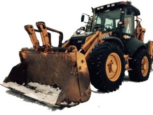

Case 595SLE, 595LSP Loader Backhoe Factory Service & Shop Manual

1,000+ pages, bookmarked, Searchable, Printable, high quality PDF
7-22470GB – 595SLE, 595LSP Loader Backhoe Service Manual.pdf – 536 pages
7-22470GB – 595SLE (Super LE), 595LSP Loader Backhoe Service Manual.pdf – 580 pages
7-26630GB – 595 SLE, 595 LSP Training Manual.pdf – 44 pages
7-26620GB – 595LE:SLE:LSP Electrical Schematic:Wiring Diagram.pdf – 195 pages

Complete workshop & service manual with electrical wiring diagrams for Case 595SLE, 595LSP Loader Backhoe. It’s the same service manual used by dealers that guaranteed to be fully functional and intact without any missing page.

This Case 595SLE, 595LSP Loader Backhoe service & repair manual (including maintenance, overhaul, disassembling & assembling, adjustment, tune-up, operation, inspecting, diagnostic & troubleshooting…) is divided into different sections. Each section covers a specific component or system with detailed illustrations. A table of contents is placed at the beginning of each section. Pages are easily found by category, and each page is expandable for great detail. The printer-ready PDF documents work like a charm on all kinds of devices.

EXCERPT:
595SLE/595LSP LOADER BACKHOE SERVICE MANUAL
Table of contents
DIVISION/SECTION SECTION N° REFERENCE N°
1 GENERAL
Standard torque specifications and loctite product chart …1001 7-79451GB
Fluids and lubricants …1002 7-22480GB
2 ENGINE
Engine and radiator removal and installation…2000 7-21290GB
Specifications details …2401 7-26610GB
3 FUEL SYSTEM
4 ELECTRICAL
Electrical schematic …4001 7-26620GB
Battery…4003 7-21330GB
Starter motor …4004 7-21340GB
Removal and installation of electrical components …4005 7-21350GB
Alternator …4007 7-23790GB
Steering, loader and backhoe calibration…4008 7-26530GB
5 STEERING
Removal and installation of steering components …5000 7-23810GB
Steering specifications, pressure checks and troubleshooting …5001 7-21900GB
Steering control valve …5002 7-21390GB
Steering cylinder …5003 7-21400GB
Front axle, four wheel drive machine/four wheel steer machine…5007 7-21890GB
6 POWER TRAIN
Removal and installation of power train components …6000 7-22540GB
Transmission specifications, pressure checks and troubleshooting …6002 7-21430GB
Wheels and tyres …6003 7-22550GB
Gear box …6007 7-22560GB
Rear axle-four whell steer …6008 7-21600GB
7 BRAKES
Removal and installation of brake components …7000 7-23840GB
Disassembly and assembly of brake components…7003 7-23190GB
8 HYDRAULICS
Removal and installation of hydraulic components…8001 7-23210GB
Hydraulic specifications, troubleshooting and pressure checks…8002 7-26630GB
Cleaning the hydraulic system…8003 7-21520GB
Hydraulic pump and unloader valve…8004 7-23250GB
Loader control valve…8005 7-23280GB
Cylinders …8006 7-26120GB
Backhoe control valve…8007 7-23290GB
Extending dipperstick control valve…8008 7-21560GB
Priority demand valve …8010 7-21570GB
9 MOUNTED/EQUIPMENT
Pedals and levers …9001 7-23360GB
Loader…9006 7-26140GB
Cab and Rops …9007 7-26600GB
Backhoe …9008 7-26710GB
Seat and seat belt …9009 7-23830GB
Removal and installation of components …9011 7-23850GB

THROTTLE ADJUSTMENT
Adjustment procedure
1. Park the machine on a level surface.
2. Switch off the engine.
3. Move the hand throttle lever to the max. rpm position.
4. Check that the throttle lever on the engine fuel pump is in contact with the top screw (9).
5. If the throttle lever is not in contact with the stop screw (9), adjust the length of the cable (5) using the locknuts (6) at the throttle bracket (7).
6. Set the throttle pedal (1) to the max. rpm position and hold it there.
7. Check that the gap between the throttle pedal (1) and the stop bolt (11) on the mounting bracket (10) is less than 0 to 0.5 mm.
8. If the gap between the throttle pedal (1) and the stop bolt (11) is greater than 0 to 0.5 mm adjust the length of the stop bolt (11) to bring the gap within limits.
9. Move the hand throttle lever (2) to the min. rpm position.
10. Start the engine.
11. Check that the engine rpm is between 550 and 750 rpm.
12. If the engine rpm is incorrect, adjust the stop screw on the engine fuel pump to bring the rpm within limits.
13. Make sure that the hand throttle lever (2) is in contact with the stop on the hand throttle assembly.

Posted on

Case 590 Loader Backhoe Factory Service & Shop Manual


Download Link

INSTANT DOWNLOAD (add to cart)


OLYMPUS DIGITAL CAMERA

Case 590 Loader Backhoe Factory Service & Shop Manual

1,128 pages, bookmarked, Searchable, Printable, high quality PDF
Case 590 Loader Backhoe Service Manual; 1,128 pages

Complete workshop & service manual with electrical wiring diagrams for Case 590 Loader Backhoe. It’s the same service manual used by dealers that guaranteed to be fully functional and intact without any missing page.

This Case 590 Loader Backhoe service & repair manual (including maintenance, overhaul, disassembling & assembling, adjustment, tune-up, operation, inspecting, diagnostic & troubleshooting…) is divided into different sections. Each section covers a specific component or system with detailed illustrations. A table of contents is placed at the beginning of each section. Pages are easily found by category, and each page is expandable for great detail. The printer-ready PDF documents work like a charm on all kinds of devices.

EXCERPT:
Inspection
1. Discard the parts that were removed from the gland, piston rod assembly, and the tube (10).
2. Clean all parts in cleaning solvent.
3. Inspect the gland, piston rod assembly, and the tube for damage and wear. These parts are not serviced separately, if these parts need to be replaced, a new steering cylinder must be used.
Assembly
See the cross sectional view of the steering cylinder on page 10.
1. Install a new seal (4) in the gland (5). The lip of the seal (4) must be toward the inside of the gland (5).
2. Install a new backup ring (3) next to the gland (5).
3. Install a new wiper (2) in the gland (5). The lip of the wiper (2) must be toward the outside of the gland (5).
4. Install a new 0-ring (6) in the groove on the outside of the gland (5).
5. Fasten the piston rod assembly (7) in a vise with soft jaws.
6. Install a new backup ring (14) in the center groove of the piston rod assembly (7).
7. Install a new seal (8) on top of the backup ring (14) in the center groove of the piston rod assembly (7).
8. Install a new wear ring (9) in the groove on each side of the seal (8).
9. Lubricate the seal (8) and wear rings (9) with clean oil.
Use a piston ring compression tool to hold the new wear rings (9) in place.
10. Start the tube (10) onto the piston rod assembly (7). Push the tube (1 0) onto the piston rod assembly (7) until the compression tool is pushed off the piston rod assembly (7). Be careful not to damage the wear rings (9) and the seal (8).
11. Fasten the tube (10) in a vise with soft jaws. Push the piston rod assembly (7) all the way into the tube (10).
12. Lubricate the wiper (2), backup ring (3), seal (4), and 0-ring (6) on the gland (5) with clean oil.
13. Install the gland (5) on the piston rod assembly (7) and push the gland (5) against the tube (10).

Posted on

John Deere 310J Backhoe Loader Technical Manual (Operation & Test) (TM10846)


Download Link

INSTANT DOWNLOAD (add to cart)


1,001 pages, bookmarked, Searchable, Printable, high quality PDF

TM10846 – 310J Backhoe Loader Operation & Test Manual
TABLE OF CONTENTS
Foreword
9000 – General Information
9001 – Diagnostic Trouble Codes (DTC)
9005 – Operational Checkout Procedure
9010 – Engine
9015 – Electrical System
9020 – Power Train
9025 – Hydraulic System
9031 – Heating and Air Conditioning

Complete Technical manual (Operation & Test Manual) for John Deere 310J Backhoe Loader. It’s the same manual used by dealers that guaranteed to be fully functional and intact without any missing page. This service manual divided into different sections. Each section covers a specific component or system with detailed illustrations. A table of contents is placed at the beginning of each section. Pages are easily found by category, and each page is expandable for great detail. The printer-ready PDF documents work like a charm on all kinds of devices.

EXCERPT:
Mechanical Front Wheel Drive (MFWD) Gear and Pinion Check
Action:
Drive machine at transport speed with mechanical front wheel drive (MFWD) engaged, then disengage.
LISTEN: Does mechanical front wheel drive (MFWD) “whine” when disengaged?
NOTE:
It is normal for mechanical front wheel drive (MFWD) to “whine” when engaged at transport speeds.
Result:
YES: Go to next check.
NO: If mechanical front wheel drive (MFWD) “whines”, check oil levels and fill to correct level.
24 Ride Control System Check (If Equipped)
Action:
Run engine at slow idle.
Turn ride control ON.
Raise loader boom to maximum height.
Power boom down half-way to the ground.
Stop suddenly by releasing the joystick.
LOOK: Is boom cushioned when joystick is released?

Posted on

Case 580ST, 590ST, 695ST Stage IIIB Tractor Backhoe Loader Factory Service & Shop Manual


Download Link

INSTANT DOWNLOAD (add to cart)


Complete workshop & service manual with electrical wiring diagrams for Case 580ST, 590ST, 695ST Stage IIIB Tractor Backhoe Loader. It’s the same service manual used by dealers that guaranteed to be fully functional and intact without any missing page.

This Case 580ST, 590ST, 695ST Stage IIIB Tractor Backhoe Loader service & repair manual (including maintenance, overhaul, disassembling & assembling, adjustment, tune-up, operation, inspecting, diagnostic & troubleshooting…) is divided into different sections. Each section covers a specific component or system with detailed illustrations. A table of contents is placed at the beginning of each section. Pages are easily found by category, and each page is expandable for great detail. The printer-ready PDF documents work like a charm on all kinds of devices.

2,021+ pages, bookmarked, Searchable, Printable, high quality PDF
47847146 – 580ST, 590ST, 695ST Stage IIIB Tractor (T4) Backhoe Loader Service Manual

EXCERPT:
Contents
INTRODUCTION
Machine completion and equipment .. 05
[05.102] Machine completion . . 05.1
Engine… 10
[10.001] Engine and crankcase . . 10.1
[10.501] Exhaust Gas Recirculation (EGR) – Diesel Particulate Filter (DPF) exhaust
treatment . . 10.2
[10.400] Engine cooling system . . 10.3
[10.304] Engine lubrication system . . 10.4
Transmission.. 21
[21.112] Power shuttle transmission. . 21.1
[21.134] Power shuttle transmission external controls . . 21.2
[21.104] Power shuttle transmission lubrication system. . 21.3
[21.154] Power shuttle transmission internal components . . 21.4
[21.113] Powershift transmission . . 21.5
[21.135] Powershift transmission external controls. . 21.6
[21.105] Powershift transmission lubrication system . . 21.7
[21.155] Powershift transmission internal components. . 21.8
[21.145] Gearbox internal components. . 21.9
Four-Wheel Drive (4WD) system .. 23
[23.314] Drive shaft. . 23.1
Front axle system … 25
[25.100] Powered front axle . . 25.1
[25.102] Front bevel gear set and differential . . 25.2
[25.108] Final drive hub, steering knuckles, and shafts . . 25.3
Rear axle system.. 27
[27.100] Powered rear axle. . 27.1
[27.106] Rear bevel gear set and differential . . 27.2
[27.120] Planetary and final drives . . 27.3
Brakes and controls .. 33
[33.202] Hydraulic service brakes . . 33.1
[33.110] Parking brake or parking lock . . 33.2
Hydraulic systems… 35
[35.000] Hydraulic systems. . 35.1
[35.300] Reservoir, cooler, and filters. . 35.2
[35.104] Fixed displacement pump . . 35.3
[35.106] Variable displacement pump . . 35.4
[35.102] Pump control valves. . 35.5
[35.350] Safety and main relief valves . . 35.6
[35.128] Auxiliary hydraulic function control . . 35.7
[35.355] Hydraulic hand control . . 35.8
[35.352] Hydraulic swing system . . 35.9
[35.724] Front loader hydraulic system control . . 35.10
[35.701] Front loader arm hydraulic system . . 35.11
[35.723] Front loader bucket hydraulic system . . 35.12
[35.726] Excavator and backhoe hydraulic controls. . 35.13
[35.736] Boom hydraulic system . . 35.14
[35.737] Dipper hydraulic system. . 35.15
[35.738] Excavator and backhoe bucket hydraulic system . . 35.16
[35.739] Swing arm hydraulic system . . 35.17
[35.703] Stabilizer hydraulic system. . 35.18
[35.740] Telescopic arm hydraulic system. . 35.19
Frames and ballasting … 39
[39.100] Frame . . 39.1
[39.140] Ballasts and supports . . 39.2
Steering… 41
[41.101] Steering control . . 41.1
[41.106] Tie rods. . 41.2
[41.200] Hydraulic control components. . 41.3
[41.206] Pump . . 41.4
[41.216] Cylinders . . 41.5
Wheels.. 44
[44.511] Front wheels. . 44.1
[44.520] Rear wheels . . 44.2
Cab climate control … 50
[50.100] Heating . . 50.1
[50.104] Ventilation . . 50.2
[50.200] Air conditioning. . 50.3
Electrical systems … 55
[55.100] Harnesses and connectors. . 55.1
[55.201] Engine starting system . . 55.2
[55.301] Alternator. . 55.3
[55.302] Battery. . 55.4
[55.011] Fuel tank system . . 55.5
[55.012] Engine cooling system . . 55.6
[55.640] Electronic modules . . 55.7
[55.512] Cab controls. . 55.8
[55.047] Steering control system . . 55.9
[55.408] Warning indicators, alarms, and instruments . . 55.10
[55.991] Telematics . . 55.11
[55.DTC] FAULT CODES. . 55.12
Front loader and bucket… 82
[82.100] Arm. . 82.1
[82.300] Bucket . . 82.2
Booms, dippers, and buckets … 84
[84.114] Boom pivoting support . . 84.1
[84.910] Boom . . 84.2
[84.912] Dipper arm . . 84.3
[84.100] Bucket . . 84.4
Platform, cab, bodywork, and decals … 90
[90.105] Machine shields and guards . . 90.1

Cab climate control – Air conditioning
Air conditioning – Adjust
Adjusting sensor of air-conditioner temperature
Remove the seat mounting plate.
The temperature adjusting sensor (2) is mounted to the side of the blower motor assembly.
Carefully pull and disconnect the switch wiring at the connector.
Remove temperature control switch and replace as required.

Posted on

Case 580SR, 580SR+, 590SR, 695SR Loader Backhoe Service Manual Factory Service & Shop Manual


Download Link

INSTANT DOWNLOAD (add to cart)


Complete workshop & service manual in English and Spanish, with electrical wiring diagrams for Case 580SR, 580SR+, 590SR, 695SR Loader Backhoe. It’s the same service manual used by dealers that guaranteed to be fully functional and intact without any missing page.

This service & repair manual for Case 580SR, 580SR+, 590SR, 695SR Loader Backhoe (including maintenance, overhaul, disassembling & assembling, adjustment, tune-up, operation, inspecting, diagnostic & troubleshooting…) is divided into different sections. Each section covers a specific component or system with detailed illustrations. A table of contents is placed at the beginning of each section. Pages are easily found by category, and each page is expandable for great detail. The printer-ready PDF documents work like a charm on all kinds of devices.

7,500+ pages, bookmarked, Searchable, Printable, high quality PDF

“9-91442 – Chargeuse Pelleteuse Case 580SR-590SR-695SM-695SR Service Manuel (FR).pdf” – 998 pages
“9-91452 – Backhoe Loader Case 580SR-590SR-695SM-695SR Service Manual (EN).pdf” – 996 pages
“9-91462 – Baggerlader Case 580SR-590SR-695SM-695SR Reparaturhandbuch (DE).pdf” – 990 pages
“9-91472 – Cargadoras Excavadoras Case 580SR-590SR-695SM-695SR Manuel de Reparacion (ES).pdf” – 996 pages

“”87570830A.pdf””
Case580 Super R – 590 Super R – 695 Super R Loader Backhoe Service Manual (EN); 1,022 pages; Print No. 87570830A

“87643852B_EN.pdf”
Case 580SR, 580SR+, 590SR, 695SR Series 3 Loader Backhoe Service Manual; 1,068 pages; Print No. 87643852B

“580 Super R – 590 Super R – 695 Super R”
MANUAL DE INSTRUCCIONES Y REPARACIONES COMPLETO El Manual de Servicio completo consta de dos volúmenes:
Z 580 Super R – 590 Super R – 695 Super R Manual de Servicio “EXCAVADORAS
CARGADORAS”
Z 580 Super R – 590 Super R – 695 Super R Manual de Servicio “Motor”
Los Manuales de Servicio para “Excavadoras Cargadoras” y “Motor” contienen la información técnica necesaria para llevar a cabo operaciones de mantenimiento y reparaciones sobre la máquina y sobre el motor, así como sobre las herramientas necesarias para realizar dichas operaciones, el mantenimiento ordinario, los procedimientos de conexión y desconexión, el montaje y el desmontaje de las distintas partes.

“590 Super R – 695 Super R”
MANUAL DE INSTRUCCIONES Y REPARACIONES COMPLETO
El Manual de Servicio completo consta de dos volúmenes:
Z 590 Super R – 695 Super R Manual de Servicio “EXCAVADORAS CARGADORAS”
Z 590 Super R – 695 Super R Manual de Servicio “Motor”
Los Manuales de Servicio para “Excavadoras Cargadoras” y “Motor” contienen la información técnica necesaria para llevar a cabo operaciones de mantenimiento y reparaciones sobre la máquina y sobre el motor, así como sobre las herramientas necesarias para realizar dichas operaciones, el mantenimiento ordinario, los procedimientos de conexión y desconexión, el montaje y el desmontaje de las distintas partes.

EXCERPT:
TABLE OF CONTENTS
SECTION 00 – SAFETY PRECAUTIONS
SECTION 01 – MAINTENANCE
SECTION 02 – TECHNICAL SPECIFICATIONS
1. LOADER BACKHOE MODELS ……. 3
2. IDENTIFICATION OF MAIN COMPONENTS……. 4
3. SPECIFICATIONS……. 6
3.1 DIESEL ENGINE ……. 6
3.2 TRANSMISSION…….. 8
3.3 AXLES ……. 9
3.4 BRAKES ……. 9
3.5 STEERING……… 10
3.6 HYDRAULIC SYSTEM …….. 10
3.7 FRONT COUNTERWEIGHT ……. 10
3.8 NOISE AND VIBRATION LEVELS …….. 11
3.9 BUCKETS……. 11
3.10 TYRES……. 12
4. DIMENSIONS AND PERFORMANCE……. 13
4.1 LOADER ATTACHMENT DIMENSIONS AND PERFORMANCE …….. 13
4.2 DIMENSIONS AND PERFORMANCE OF LOADER ATTACHMENT WITH FORKS……. 19
4.3 BACKHOE ATTACHMENT DIMENSIONS AND PERFORMANCE ……… 20
5. BACKHOE ATTACHMENT LIFTING CAPACITY…….. 26
6. MAXIMUM LIFTING LOADS……. 29
6.1 LOADER ATTACHMENT MAXIMUM LIFTING LOAD TABLE …….. 29
6.2 BACKHOE ATTACHMENT MAXIMUM LIFTING LOAD TABLE ……. 30
7. SUPPLY SUMMARY TABLE……. 31
SECTION 17 – TORQUE CONVERTERS
1. POWERSHUTTLE TORQUE CONVERTER…….. 3
1.1 DESCRIPTION AND OPERATION……. 3
1.2 SPECIFICATIONS……. 4
1.3 OVERHAUL ……… 4
1.4 INSPECTION……. 4
1.5 DISASSEMBLY AND ASSEMBLY…….. 5
1.6 STALL TEST…….. 5
1.7 FAULT FINDING…….. 6
2. POWERSHIFT TORQUE CONVERTER…….. 7
2.1 DESCRIPTION AND OPERATION……. 7
2.2 SPECIFICATIONS……. 8
2.3 OVERHAUL ……… 8
2.4 INSPECTION……. 9
2.5 DISASSEMBLY AND ASSEMBLY…….. 9
2.6 STALL TEST……. 11
2.7 FAULT FINDING…….. 12
SECTION 21 – TRANSMISSION
1. POWERSHUTTLE TRANSMISSION “TURNER MODEL COM-T4-2025”……… 3
1.1 SPECIFICATIONS ……. 3
1.2 MOUNTING SCREW TORQUE…….. 5
1.3 TRANSMISSION CONTROLS……. 6
1.4 LUBRICATION……… 11
1.5 TRANSMISSION OIL FLOW AND SUPPLY……… 12
1.6 TRANSMISSION HYDRAULIC VALVES AND PRESSURE TEST POINTS……. 18
1.7 TRANSMISSION POWER FLOW……. 19
1.8 TRANSMISSION 2WD COMPONENTS…….. 23
1.9 TRANSMISSION 4WD COMPONENTS…….. 26
1.10 TRANSMISSION REMOVAL …….. 31
1.11 DISASSEMBLY AND ASSEMBLY……. 32
1.12 FAULT FINDING……… 90
1.13 SPECIAL TOOLS…….. 93
2. POWERSHIFT TRANSMISSION “DANA T16000” ……… 94
2.1 SPECIFICATIONS …….. 94
2.2 CONTROLS ……. 95
2.3 LUBRICATION……. 105
2.4 PRESSURE SPECIFICATIONS AND CHECK POINTS……. 106
2.5 TRANSMISSION COOLER…….. 108
2.6 HYDRAULIC DIAGRAM…….. 109
2.7 OPERATION……. 110
2.8 POWER FLOWS……… 117
2.9 GEAR AND CLUTCH LAY OUT ……. 132
2.10 TRANSMISSION REMOVAL AND INSTALLATION……. 133
2.11 TRANSMISSION COMPONENTS…….. 137
2.12 DISASSEMBLY AND ASSEMBLY…….. 155
2.13 SPECIAL TOOLS……. 264
2.14 FAULT FINDING……. 265
2.15 FAULT FINDING……. 267
SECTION 25 – FRONT AXLES
1. FRONT AXLE 2WD “CARRARO” ……. 3
1.1 SPECIFICATIONS ……. 3
1.2 DISASSEMBLY AND ASSEMBLY…….. 6
1.3 FAULT FINDING…….. 24
2. FRONT AXLE 4WD “CARRARO” ……. 26
2.1 SPECIFICATIONS …….. 26
2.2 DISASSEMBLY AND ASSEMBLY……… 31
2.3 FAULT FINDING…….. 77
3. FRONT AXLE 4WS “CARRARO” ……. 80
3.1 SPECIFICATIONS …….. 80
3.2 DISASSEMBLY AND ASSEMBLY……… 84
3.3 FAULT FINDING……… 137
4. SPECIAL TOOLS……. 140
SECTION 27 – REAR AXLE
1. REAR AXLE 2WS……. 3
1.1 DESCRIPTION AND OPERATION……… 3
1.2 SPECIFICATIONS……. 6
1.3 DISASSEMBLY AND ASSEMBLY…….. 8
1.4 FAULT FINDING…….. 27
2. REAR AXLE 4WS “CARRARO”…….. 28
2.1 SPECIFICATIONS…….. 28
2.2 DISASSEMBLY AND ASSEMBLY……… 32
2.3 FAULT FINDING…….. 81
3. SPECIAL TOOLS……. 84
SECTION 33 – BRAKES SYSTEM
1. SPECIFICATIONS……. 3
2. PARKING BRAKE……. 6
2.1 PARKING BRAKE ADJUSTMENT ……. 7
3. BRAKE CYLINDERS …….. 8
4. OIL BRAKE TANK ……. 13
5. BLEEDING PROCEDURE……. 13
SECTION 35 – HYDRAULIC SYSTEM
1. HYDRAULIC DIAGRAMS……. 3
1.1 HYDRAULIC DIAGRAM – 2WS SIDESHIFT MECHANICAL MODELS……… 3
1.2 HYDRAULIC DIAGRAM – 2WS SIDESHIFT PILOT MODELS……. 5
1.3 HYDRAULIC DIAGRAM – 4WS SIDESHIFT MECHANICAL MODELS……… 7
1.4 HYDRAULIC DIAGRAM – 4WS SIDESHIFT PILOT MODELS……. 9
1.5 HYDRAULIC DIAGRAM – 4WS CENTER PIVOT PILOT MODELS ……… 11
2. HYDRAULIC PUMP…….. 13
2.1 DESCRIPTION AND OPERATION…….. 13
2.2 SPECIFICATIONS…….. 13
2.3 LOAD SENSING VALVE …….. 16
2.4 REMOVAL ……… 18
2.5 COMPONENTS ……. 19
2.6 DISASSEMBLY AND ASSEMBLY……… 20
3. CONTROL VALVES ……. 24
3.1 CONTROL VALVES “REXROTH” (MECHANICAL MODELS) …….. 24
3.2 “REXROTH” CONTROL VALVES (PILOT MODELS) …….. 40
3.3 SOLENOID VALVE FOR PILOTING THE BACKHOE CONTROL VALVE
(WITH HYDRAULIC CONTROL) ……… 49
3.4 RELIEF VALVES ……. 52
3.5 ACCUMULATOR “GLIDE RIDE” PARKER……. 60
4. HYDRAULIC SWING SYSTEM …….. 63
4.1 DESCRIPTION AND OPERATION…….. 63
4.2 HYDRAULIC OIL FLOW……. 64
5. HYDRAULIC CYLINDERS……. 66
5.1 LOADER ATTACHMENT BOOM CYLINDER ……… 67
5.2 LOADER BUCKET CYLINDER ……. 72
5.3 4X1 LOADER BUCKET CYLINDER……. 76
5.4 BACKHOE BOOM CYLINDER ……. 79
5.5 BACKHOE ATTACHMENT DIPPER CYLINDER ……. 83
5.6 BACKHOE BUCKET CYLINDER…….. 87
5.7 TELESCOPIC CYLINDER ……… 91
5.8 4WS STABILIZER CYLINDER – CENTER PIVOT……… 95
5.9 STABILIZER CYLINDER – SIDESHIFT ……. 99
5.10 SWING CYLINDER……. 103
5.11 BACKHOE ATTACHMENT SIDESHIFT CYLINDER – SIDESHIFT……… 107
5.12 SPECIAL TOOLS……. 108
6. HYDRAULIC CONTROL LEVERS……. 109
6.1 SPECIFICATIONS ……. 109
6.2 DESCRIPTION AND OPERATION……. 110
6.3 DISASSEMBLY AND ASSEMBLY……. 113
6.4 CONTROL LEVER VALVE …….. 116
7. FAULT FINDING…….. 119
7.1 PRELIMINARY CHECKS……… 119
7.2 FAULT FINDING……… 120
SECTION 39 – CHASSIS
1. DESCRIPTION AND OPERATION……. 3
2. REMOVAL AND INSTALLATION COMPONENTS…….. 5
2.1 COMPONENTS WITHIN THE CHASSIS……. 5
2.2 COMPONENTS BELOW THE CHASSIS …….. 6
2.3 COMPONENTS ATTACHED OUTSIDE THE CHASSIS……. 8
2.4 COMPONENTS ATTACHED ON THE CHASSIS……. 9
2.5 MOUNTING SCREW TORQUE……. 11
SECTION 41 – STEERING SYSTEM
1. STEERING SYSTEM 2WS …….. 4
2. STEERING SYSTEM 4WS …….. 7
3. POWER STEERING ……. 12
3.1 SPECIFICATIONS …….. 13
3.2 COMPONENTS ……. 15
3.3 DISASSEMBLY AND ASSEMBLY……… 16
3.4 SPECIAL TOOLS……. 33
3.5 FAULT FINDING…….. 33
SECTION 50 – CAB HEATING AND AIR CONDITIONING
1. SPECIFICATIONS ……. 3
2. CAB HEATING……… 5
2.1 DESCRIPTION AND OPERATION……. 5
3. AIR CONDITIONING……. 12
3.1 PRINCIPALS OF AIR CONDITIONING ……. 12
3.2 SAFETY PRECAUTIONS ……. 16
3.3 CONTROLS AND OPERATION ……… 17
3.4 FAULT FINDING AND TESTING…….. 26
3.5 FLUSHING THE SYSTEM……… 44
3.6 EVACUATING THE SYSTEM……… 46
3.7 CHARGING THE SYSTEM…….. 47
3.8 COMPONENTS OVERHAUL ……… 48
3.9 COMPRESSOR……. 53
3.10 SPECIAL TOOLS…….. 67
SECTION 55 – ELECTRICAL SYSTEM
1. GENERALITIES……. 3
1.1 TEMPORARY WIRING HARNESS REPAIR……. 3
1.2 FAULT FINDING…….. 4
2. ELECTRICAL DIAGRAMS……… 5
2.1 ELECTRICAL DIAGRAMS – POWERSHUTTLE ROPS (580SR)…….. 5
2.2 ELECTRICAL DIAGRAMS – POWERSHUTTLE CAB (580SR)……. 20
2.3 ELECTRICAL DIAGRAMS – POWERSHIFT CAB (580SR)……. 36
2.4 ELECTRICAL DIAGRAMS – POWERSHUTTLE CAB (580SR+/590SR) ……. 54
2.5 ELECTRICAL DIAGRAMS – POWERSHIFT CAB (590SR)……. 69
2.6 ELECTRICAL DIAGRAMS – 4WS POWERSHIFT CAB (695SR)……… 84
3. CONTROLS AND INSTRUMENTS ……… 100
3.1 FRONT CONTROL PANELS (580SR / 590SR) ……. 100
3.2 FRONT CONTROL PANELS (695SR) …….. 102
3.3 SIDE INSTRUMENT CLUSTER PANEL (580SR)……. 104
3.4 SIDE INSTRUMENT CLUSTER PANEL (580SR+ / 590SR / 695SR)……. 106
3.5 SIDE INSTRUMENT CLUSTER (580SR)……. 108
3.6 SIDE INSTRUMENT CLUSTER (580SR+ / 590SR / 695SR)…….. 110
3.7 IMMOBILISER CIRCUIT……. 112
4. DIAGNOSTIC DISPLAY (580SR+ / 590SR / 695SR) ……… 113
4.1 SYMBOLS…….. 114
4.2 SETUP MENU ……. 115
4.3 PROCEDURE ABOUT SELF TEST ……. 116
4.4 ON BOARD ERROR CODE RETRIEVAL ……. 117
4.5 BACKLIGHTING AND DIMMING……… 118
4.6 WORK HOURS…….. 119
4.7 FUNCTIONAL DESCRIPTION ……… 120
4.8 WARNING SYSTEM……. 124
4.9 MAINTENANCE……. 126
4.10 WARNING MESSAGES …….. 127
5. STARTING SYSTEM……… 134
5.1 DESCRIPTION AND OPERATION……. 134
5.2 FAULT FINDING……… 135
5.3 STARTER MOTOR……… 138
6. ALTERNATOR…….. 144
6.1 SPECIFICATIONS……. 144
6.2 DESCRIPTION AND OPERATION……. 144
6.3 COMPONENTS ……. 146
6.4 REMOVAL ……. 147
6.5 PRELIMINARY CHECK AND TESTS…….. 148
6.6 FAULT FINDING……… 157
7. BATTERY …….. 158
7.1 SPECIFICATIONS……. 158
7.2 DESCRIPTION AND OPERATION……. 158
7.3 BATTERY REPLACEMENT ……… 159
7.4 MAINTENANCE……. 161
7.5 TESTS ……. 163
7.6 CONNECTING A BOOSTER BATTERY …….. 165
7.7 BATTERY MASTER SWITCH ……. 165
8. COMPONENT TESTING ……. 166
8.1 GENERAL INTRODUCTION …….. 166
8.2 COMPONENT TESTING……… 167
8.3 GROUND POINTS……. 167
8.4 ALTERNATOR……. 170
8.5 TRANSMISSIONS ……. 170
8.6 PARKING BRAKE SWITCH……. 174
8.7 CAB…….. 175
8.8 4WD SWITCH…….. 180
8.9 BRAKE PEDAL SWITCHES ……… 180
8.10 BRAKE OIL LEVEL WARNING LAMP……. 181
8.11 FRONT WORK LAMP SWITCH (1) – REAR WORK LAMP SWITCH (2) MAIN LIGHT SWITCH…. 181
8.12 HAZARD SWITCH …….. 182
8.13 HAZARD WARNING LIGHT RELAY…….. 182
8.14 MULTI FUNCTION SWITCH……. 183
8.15 FRONT WINDSHIELD WIPER MOTOR (1) – REAR WINDSHIELD WIPER MOTOR (2) …….. 183
8.16 4WS – STEERING SELECTOR SWITCH ……… 184
8.17 STEERING CONTROL UNIT……. 185
8.18 4WS REAR AXLE STEERING SENSOR……. 187
8.19 4WS FRONT AXLE STEERING SENSOR ……. 187
8.20 STEERING SOLENOID VALVE……… 188
8.21 DIFFERENTIAL LOCK SWITCH (1) …….. 189
8.22 LOADER …….. 190
8.23 BACKHOE……. 193
SECTION 82 – LOADER
1. LOADER ATTACHMENT CONTROLS…….. 3
1.1 LOADER ATTACHMENT OPERATION……… 3
2. LOADER BUCKET SELF LEVELING ……. 6
3. LOADER ATTACHMENT SAFETY STRUT……. 7
4. LOADER BUCKET REMOVAL …….. 8
5. LOADER REMOVAL……. 11
SECTION 84 – BACKHOE
1. DESCRIPTION AND OPERATION……. 3
2. BACKHOE ATTACHMENT MECHANICAL CONTROLS VERSION …….. 6
3. BACKHOE ATTACHMENT HYDRAULIC CONTROLS …….. 15
4. REMOVAL AND INSTALLATION ……. 17
4.1 CENTER PIVOT BACKHOE ATTACHMENT DISASSEMBLY…….. 17
4.2 BACKHOE ATTACHMENT DISASSEMBLY – SIDESHIFT…….. 20
4.3 BACKHOE BUCKET REMOVAL …….. 23
4.4 BUCKET TEETH REPLACEMENT…….. 23
4.5 DIPPER REMOVE…….. 24
5. TELESCOPIC DIPPER REVISION…….. 27
6. TELESCOPIC DIPPER REVISION…….. 27
7. REVISIONE DEL BRACCIO TELESCOPICO……. 27

FAULTS OTHER F12
NOT IDENTIFIED BY THE LEDS
There may be situations when an individual component develops a fault but it is not highlighted by the
LEDs. If a component is in doubt proceed to input test as follows:
Perform Input test:
This test is used to verify the inputs.
In this mode driving is possible.
NOTE: the gear position indicators on the microprocessor top cover are used to display the test information.
INPUT TEST REQUIREMENTS: the powershift lever must be in forward position. Set it to upshift and start the machine. The microprocessor shifts to the input test mode.
As shown in the table below placing the shift lever in different positions in this mode illuminates its respective LED.
IMPORTANT: selftest modes can only be started WHILE POWERING UP (ignition on). Leaving the selftest mode is done by switching OFF the power of the microprocessor.

SECCIÓN 25 – EJE DELANTERO
Extraer el soporte delantero (2) de la carcasa del eje (6).
Retirar el perno (8) con el engrassador (9).
Retirar el casquillo (3) del soporte delantero (2).
Retirar los casquillos (1) del soporte delantero (2).
Retirar el casquillo (4) y la arandela de empuje (5) de la carcasa del eje (6) solo en caso necesario.
NOTA: es conveniente calentar el casquillo (4) para facilitar este proceso; este es un proceso destructivo para el casquillo.
Introducir la arandela de empuje (14) en el soporte del diferencial.
Calentar el casquillo (13) a 110÷120 °C y montarlo con el soporte del diferencial.
NOTA: en caso necesario, montar el casquillo (13) con un cojín amortiguador y un martillo.