Posted on

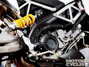
Aprilia V990 Engine Workshop Repair & Service Manual (Printable, iPad-ready PDF)

Aprilia V990 Engine Workshop Repair & Service Manual (Printable, iPad-ready PDF)

Aprilia V990 Engine Workshop Repair & Service Manual (Printable, iPad-ready PDF)


MAPRV9HOPEK
Price: $9.99 USD

Complete digital workshop service and repair manual written for your Aprilia V990 Engine. All styles covered (all models, and engines). It is in the cross-platform PDF document format so that it works like a charm on all kinds of devices.

This QUALITY manual is 100% COMPLETE and INTACT, no MISSING/CORRUPT pages/sections to freak you out! Buy from responsible seller and get INSTANT DOWNLOAD now without wasting your hard-owned money on uncertainty or surprise; this manual for Aprilia V990 Engine is exactly as described.

PRODUCT DETAILS:
Total Pages: 186 pages
File Format: PDF (Windows & Mac & Linux)
Language: English
Delivery: instant download link displayed on checkout page & emailed to you after payment
Protection: DRM-free; without any restriction
Printable: Yes

This COMPLETE full workshop service repair manual for Aprilia V990 Engine includes:
* Detailed sub-steps expand on repair procedure information
* Notes, cautions and warnings throughout each chapter pinpoint critical information.
* Numbered instructions guide you through every repair procedure step by step.
* Bold figure number help you quickly match illustrations with instructions.
* Detailed illustrations, drawings and photos guide you through every procedure.
* Enlarged inset helps you identify and examine parts in detail.
* Numbered table of contents easy to use so that you can find the information you need fast.
* This manual also makes it easy to diagnose and repair problems with your machines electrical system.
* Troubleshooting and electrical service procedures are combined with detailed wiring diagrams for ease of use.
* COMPLETE, Absolutely No Missing Pages!
* Customer Satisfaction GUARANTEED!

EXCERPT (Aprilia V990 Engine Service/Repair Manual):
INTRODUCTION
GENERAL INFORMATION
TECHNICAL INFORMATION
REMOVING/REFITTING THE COMPLETE ENGINE
FROM/TO THE VEHICLE FRAME
DISASSEMBLING THE ENGINE
WORK ON THE ENGINE INDIVIDUAL PARTS
REASSEMBLING THE ENGINE
FUEL SYSTEM, COOLING SYSTEM, ELECTRICAL SYSTEM
TROUBLESHOOTING
ANALYTICAL INDEX

4.8 REMOVING THE ALTERNATOR COVER AND ALTERNATOR SYSTEM
Carefully read 4.2 (IMPORTANT INFORMATION).
NOTE The following operations can be performed with­ out removing the engine from the frame.
A WARNING
When performing work on the ignition system:
– switch off the engine;
– disconnect the battery: always disconnect the negative pole (-) first;
– disconnect all the electrical connections;
– drain the engine oil tank completely, consult the section 2 (SERVICE AND SETTING UP) of specific vehicle workshop manual see 0.4.1 (VEHICLE WORKSHOP MANUAL);
– lock the crankshaft at the TDC of piston “1” or “2”.
♦ ESI ESZ3 E l Disconnect the connector (A) of the sta- tor (A1).
♦ EH1 H il Disconnect the connector (B) of stator (B1).
♦ Em Bali Disconnect the connector (C) from the crank­
shaft position sensor (Cl).
♦ Remove the plastic plug (D) and O-ring (E) located in
the center of the alternator cover (3).
♦ Unscrew and remove the twelve Allen screws M6 (1).

Do not mix up parts from cylinder “1” and cylinder “2” cam drive assemblies. Upon reassembly, ensure that you put all parts in their original positions.
♦ Check the flanks of the teeth on the timing gear (1), drive gears (2) and intermediate drive gears (3) for pit­ ting and wear.
♦ Check the bore (4) of the idler gears (3) for wear.
Bore (4) wear limit: max. diameter 0.788 in (20.015 mm).
♦ Check the roller bearings (5) for wear.
♦ Check the two bearing flanges (6) for wear around the
bearing support surface (7) of the roller bearings (5).
Bearing support surface (7) wear limit: min. diameter 0.629 in (15.98 mm).
♦ Check the chain guide shoe (8), chain tensioner shoe (9), chain guide (10) and chain guide bracket (11) for any traces of galling or scoring.
Max. depth of the galling or scoring traces: 0.047 in (1.2 mm).
♦ Check the teeth of the two timing chains (12) for any signs of distortion.
♦ Stretch the cam chain tight, count 20 pins (19 links), and measure the distance (13) between the centers of the first and the twentieth pin. Repeat for the second cam chain.
Distance (13) wear limit: max. 6.54 in (166.2 mm).

MAPRV9HOPEK
Price: $9.99 USD

Posted on

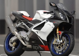
1998-2000 Aprilia RSV Mille 956X Motorcycle Workshop Repair & Service Manual (Printable, iPad-ready PDF)


1998-2000 Aprilia RSV Mille 956X  Motorcycle Workshop Repair & Service Manual (Printable, iPad-ready PDF)
1998-2000 Aprilia RSV Mille 956X Motorcycle Workshop Repair & Service Manual (Printable, iPad-ready PDF)

MAPRRM9800OPEK
Price: $9.99 USD

Complete digital workshop service and repair manual written for your 1998-2000 Aprilia RSV Mille Motorcycle. All styles covered (all models, and engines). It is in the cross-platform PDF document format so that it works like a charm on all kinds of devices.

This QUALITY manual is 100% COMPLETE and INTACT, no MISSING/CORRUPT pages/sections to freak you out! Buy from responsible seller and get INSTANT DOWNLOAD now without wasting your hard-owned money on uncertainty or surprise; this manual is exactly as described.

1998 1999 2000 Aprilia RSV Mille Motorcycle

PRODUCT DETAILS:
Total Pages: 279 pages
File Format: PDF (Windows & Mac & Linux)
Language: English
Delivery: instant download link displayed on checkout page & emailed to you after payment
Protection: DRM-free; without any restriction
Printable: Yes

This COMPLETE full workshop service repair manual includes:
* Detailed sub-steps expand on repair procedure information
* Notes, cautions and warnings throughout each chapter pinpoint critical information.
* Numbered instructions guide you through every repair procedure step by step.
* Bold figure number help you quickly match illustrations with instructions.
* Detailed illustrations, drawings and photos guide you through every procedure.
* Enlarged inset helps you identify and examine parts in detail.
* Numbered table of contents easy to use so that you can find the information you need fast.
* This manual also makes it easy to diagnose and repair problems with your machines electrical system.
* Troubleshooting and electrical service procedures are combined with detailed wiring diagrams for ease of use.
* COMPLETE, Absolutely No Missing Pages!
* Customer Satisfaction GUARANTEED!

EXCERPT (1998-2000 Aprilia RSV Mille Motorbike Service/Repair Manual):
INTRODUCTION
GENERAL INFORMATION
SERVICE AND SETTING UP
ENGINE
FUEL SUPPLY SYSTEM
COOLING SYSTEM
ELECTRICAL SYSTEM
CHASSIS PARTS
REPAIR INFORMATION
UPDATES
ANALYTICAL INDEX

2.31.1 REAR SUSPENSION
The rear suspension consists of a spring-shock absorber unit, fixed to the frame by means of a uni-ball and to the rear fork by means of lever systems.
For the setting of the vehicle attitude, the shock absorber is provided with a screw adjuster (1) for the adjustment of the hydraulic braking with extended shock absorber; a knob adjuster (2) for the adjustment of the hydraulic braking with compressed shock absorber; a ring nut for the adjustment of the spring preload (3) and a locking ring nut (4).
The riding position of the vehicle can be further altered by varying the height of the rear axle by adjusting the lock nut (5) and adjuster nut (6).
Carefully read 0.2.1 (PRECAUTIONS AND GENERAL INFORMATIONS).
Check after the first 1000 km (625 mi), and subsequently every 15000 km (9375 mi) or 16 months.
◆ Check all the rear suspension joints are working properly and that the relevant components are properly tightened.
2.31.2 ADJUSTING THE REAR SHOCK ABSORBER
The standard setting of the rear shock absorber is such as to satisfy most driving conditions at low and high speed, either with reduced load and full load.
However, it is also possible to adjust the setting accord- ing to the intended use of the vehicle.

3.6.14 COUNTERSHAFT AND COUNTERSHAFT MECHANISM
Carefully read 0.2.1 (PRECAUTIONS AND GENERAL INFORMA TIONS).
Check the wear of the countershaft:
– housing of bush (1);
wear limit min. Ø 31.980 mm;
– housing of thrust support bush (2);
wear limit min. Ø 19.990 mm;
– housing of bush (1);
permissible radial play min. Ø 0.060 mm;
– housing of support bush (2);
permissible radial play min. Ø 0.060 mm.
NOTE The radial play of the countershaft is determined
based on the following values:
maximum value of the main bush diameter in the engine casing or in the clutch cover minus the value of the bearing housing (1) or the support bush housing (2) of the countershaft.


MAPRRM9800OPEK
Price: $9.99 USD

Posted on

1994-1998 Aprilia RS250 Motorcycle Workshop Repair & Service Manual (580 Pages, Printable, iPad-ready PDF)

1994-1998 Aprilia RS250 Motorcycle Workshop Repair & Service Manual (580 Pages, Printable, iPad-ready PDF)

MAPRRS9498OPMS
Price: $9.99 USD

Complete digital workshop service and repair manual written for your 1994-1998 Aprilia RS250 Motorcycle. All styles covered (all models, and engines). It is in the cross-platform PDF document format so that it works like a charm on all kinds of devices.

This QUALITY manual is 100% COMPLETE and INTACT, no MISSING/CORRUPT pages/sections to freak you out! Buy from responsible seller and get INSTANT DOWNLOAD now without wasting your hard-owned money on uncertainty or surprise; this manual is exactly as described.

PRODUCT DETAILS:
Total Pages: 5,80 pages
File Format: PDF (Windows & Mac & Linux)
Language: English/Italian/Spanish
Delivery: instant download link displayed on checkout page & emailed to you after payment
Protection: DRM-free; without any restriction
Printable: Yes

This COMPLETE full workshop service repair manual for 1994 1995 1996 1997 1998 Aprilia RS250 Motorbike includes:
* Detailed sub-steps expand on repair procedure information
* Notes, cautions and warnings throughout each chapter pinpoint critical information.
* Numbered instructions guide you through every repair procedure step by step.
* Bold figure number help you quickly match illustrations with instructions.
* Detailed illustrations, drawings and photos guide you through every procedure.
* Enlarged inset helps you identify and examine parts in detail.
* Numbered table of contents easy to use so that you can find the information you need fast.
* This manual also makes it easy to diagnose and repair problems with your machines electrical system.
* Troubleshooting and electrical service procedures are combined with detailed wiring diagrams for ease of use.
* COMPLETE, Absolutely No Missing Pages!
* Customer Satisfaction GUARANTEED!

EXCERPT (1994-1998 Aprilia RS250 Motorcycle Service/Repair Manual):

TABlE OF CONTENTS
GENERAL INFORMATION
PERIODIC MAINTENANCE AND TUNE-UP PROCEDURES
COOLING SYSTEM
ENGINE
FUEL AND LUBRICATION SYSTEM
COOLING SYSTEM
ELECTRICAL SYSTEM
CHASSIS
SERVICING INFORMATION

ENGINE COMPONENTS INSPECTION AND SERVICING CYLINDER HEAD
Remove the carbon and clean the cylinder head. Check for scratches on the mating surface. Check the gasketed surface of the cylinder head for distortion with a straightedge gauge or faceplate and thickness gauge, taking a clearance reading at several places indicated.
If the higher of the values recorded exceeds the limit indicated, replace the head.
Service limit: 0, 1 mm
If the highest reading at any portion of the straight-edge does not exceed the limit rework the surface by rubbing it against emery paper (of about# 400) laid flat on the surface plate in a lapping manner. The gaskets surface must be smooth and perfectly flat in order to secure a tight joint. A leaky joint can be the cause of reduced power output and increased fuel consumption.

FUEL TANK AND FUEL COCK
The fuel tank is equipped with a tank cap, a fuel cock and a fuel filter. The tank cap has an air vent which allows gasoline to flow to the carburettors smoothly. The fuel cock construction is as shown in the illustrations. The fuel cock has three positions, OFF, ON and RES, each of which can be selected by operating the cock lever. With the lever in ON position (normal), the main passage opens. With the lever in RES position, an auxiliary passage opens for supplying reserve fuel. With the lever in the OFF position, both of the passages are closed.


MAPRRS9498OPMS
Price: $9.99 USD

Posted on

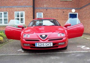
1995-2000 Alfa Romeo GTV & Spider Workshop Repair & Service Manual (2,195 Pages, Printable, iPad-ready PDF)

1995-2000 Alfa Romeo GTV & Spider Workshop Repair & Service Manual (2,195 Pages, Printable, iPad-ready PDF)

1995-2000 Alfa Romeo GTV & Spider Workshop Repair & Service Manual (2,195 Pages, Printable, iPad-ready PDF)


MARGS9500OPEK
Price: $9.99 USD

Complete digital workshop service and repair manual written for your 1995-2000 Alfa Romeo GTV & Spider. All styles covered (all models, and engines). It is in the cross-platform PDF document format so that it works like a charm on all kinds of devices.

This QUALITY manual is 100% COMPLETE and INTACT, no MISSING/CORRUPT pages/sections to freak you out! Buy from responsible seller and get INSTANT DOWNLOAD now without wasting your hard-owned money on uncertainty or surprise; this manual is exactly as described.

1995 1996 1997 1998 1999 2000 Alfa Romeo GTV & Spider

PRODUCT DETAILS:
Total Pages: 2,195 pages
File Format: PDF (Windows & Mac & Linux)
Language: English
Delivery: instant download link displayed on checkout page & emailed to you after payment
Protection: DRM-free; without any restriction
Printable: Yes

This COMPLETE full workshop service repair manual for 1995-2000 Alfa Romeo GTV & Spider includes:
* Detailed sub-steps expand on repair procedure information
* Notes, cautions and warnings throughout each chapter pinpoint critical information.
* Numbered instructions guide you through every repair procedure step by step.
* Bold figure number help you quickly match illustrations with instructions.
* Detailed illustrations, drawings and photos guide you through every procedure.
* Enlarged inset helps you identify and examine parts in detail.
* Numbered table of contents easy to use so that you can find the information you need fast.
* This manual also makes it easy to diagnose and repair problems with your machines electrical system.
* Troubleshooting and electrical service procedures are combined with detailed wiring diagrams for ease of use.
* COMPLETE, Absolutely No Missing Pages!
* Customer Satisfaction GUARANTEED!

EXCERPT (1995-2000 Alfa Romeo GTV & Spider Service/Repair Manual):
Adjustment procedure – Spider
For the Spider vehicle, the windows have the same adjustment points as the Gtv.
However, it is important to consider that the window must ensure tightness with the seals of the hood, which is, in turn, subject to possible adjustments.
It is not possible however to provide geometrical inspection dimensions as for the Gtv.
Therefore, adjustment of the window is to be carried out only for obvious malfunctions (air draughts and/or water leaks) after accurate inspection in order to locate the cause of the fault (low crossways pressure on the seals, stop in low position with respect to the hood profile, etc.).
Thus, make the most suitable correction (crossways, vertically or longitudinally) working on the corresponding adjustment points, each tine verifying the effect of the correction made until reaching the best condition possible.
For the operating procedures and the consequent effects on the window, refer to the previous paragraph on adjustment for the Gtv (previous paragraph).
At all events use the special gauge of kit 1.823.030.000 to check the correct distance between the profile of the glass and the windscreen pillar.
If an optimum condition is not reached, it is necessary to consider re-positioning the hood (see Repair Manual-Group 70- Body- Hood).

Pressing the hand held transmitter whilst your system is in the armed or partially armed condition, will place the system in the disarmed condition. A single flash of the hazard lights and the unlocking of the vehicle central door locking system will confirm this.
ARMING YOUR SYSTEM : Pressing the hand held transmitter for up to two seconds, whilst your system is in the disarmed condition will arm the system. Two flashes of the hazard lights and the locking of the vehicle central door locking will confirm this. The system LED will also begin to flash. During the first 25 seconds of the arming or partial arming condition, it is possible to test the various alarm triggers by deliberately activating
them one at a time. A brief flash of the hazard light circuit will indicate confirmation that the respective input has been received. The following protection is now in place :
1. The vehicle is immobilised 2. Door open detection3. Boot/bonnet open detection
4. Ignition hot wire detection 5. Internal movement sensor
6. Vehicle battery disconnection detection
If any of the above are activated after the arming period has elapsed, the siren will sound and the hazard lights will flash for a 30 second period.

HARD TOP SIDE MOUNTING BRACKET REMOVING
1. Open the hood, leaving the cover open.
2. Undo the cover lock front bolt.
3. Undo the lower bolt fixing the hood fastening bracket.
4. Remove the hard top side mounting bracket.

DOOR LOCKING SYSTEM
INDEX
WIRING DIAGRAM . . . . . . . . . . . . . . . . . . . . . . . . . . . . . . . . . 15-2
GENERAL DESCRIPTION . . . . . . . . . . . . . . . . . . . . . . . . . . . . . . . . . . 15-3
FUNCTIONAL DESCRIPTION . . . . . . . . . . . . . . . . . . . . . . . . . . . . . . . . 15-3
LOCATION OF COMPONENTS . . . . . . . . . . . . . . . . . . . . . . . . . . . . . . . 15-4
FAULTFINDING TABLE . . . . . . . . . . . . . . . . . . . . . . . . . . . . . . . . . 15-5
CHECKING COMPONENTS . . . . . . . . . . . . . . . . . . . . . . . . . . . . . . . . . 15-5


MARGS9500OPEK
Price: $9.99 USD

Posted on

2005-2010 Alfa Romeo Brera/Spider Workshop Repair & Service Manual

2005-2010 Alfa Romeo Brera/Spider Workshop Repair & Service Manual

2005-2010 Alfa Romeo Brera/Spider Workshop Repair & Service Manual


MARBS0510OMMK
Price: $19.99 USD

Complete digital workshop service and repair manual written for your 2005-2010 Alfa Romeo Brera/Spider. All styles covered (all models, and engines).

This QUALITY manual for 2005-2010 Alfa Romeo Brera/Spider is 100% COMPLETE and INTACT, no MISSING/CORRUPT pages/sections to freak you out! Buy from responsible seller and get INSTANT DOWNLOAD now without wasting your hard-owned money on uncertainty or surprise; this manual is exactly as described.

PRODUCT DETAILS:
Total Pages: 675 MB
File Format: ISO (Windows)
Delivery: instant download link displayed on checkout page & emailed to you after payment
Protection: DRM-free; without any restriction
Printable: Yes

MAKE: Alfa Romeo
MODEL: Brera/Spider (Type 939) (2.2 JTS, 3.2 JTS, 2.4 JTD 20V)
YAER: 2005 2006 2007 2008 2009 2010
LANGUAGE: CZ/EN/DE/ES/FR/GK/IT/NL/PL/PT/TR

This COMPLETE full workshop service repair manual for 2005-2010 Alfa Romeo Brera/Spider includes:
* Detailed sub-steps expand on repair procedure information
* Notes, cautions and warnings throughout each chapter pinpoint critical information.
* Numbered instructions guide you through every repair procedure step by step.
* Bold figure number help you quickly match illustrations with instructions.
* Detailed illustrations, drawings and photos guide you through every procedure.
* Enlarged inset helps you identify and examine parts in detail.
* Numbered table of contents easy to use so that you can find the information you need fast.
* This manual also makes it easy to diagnose and repair problems with your machines electrical system.
* Troubleshooting and electrical service procedures are combined with detailed wiring diagrams for ease of use.
* COMPLETE, Absolutely No Missing Pages!
* Customer Satisfaction GUARANTEED!

EXCERPT (2005-2010 Alfa Romeo Brera/Spider Service/Repair Manual):

10 ENGINE
18 CLUTCH UNIT
21 GEARBOX UNIT
27 AXLE
33 BRAKES
41 STEERING UNIT
44 SUSPENSION AND WHEELS
50 AUXILIARY UNITS
55 ELECTRICAL EQUIPMENT
70 FITTINGS
72 PANELS AND FRAMES

1008 POWER UNIT SUPPORTS
1012 ENGINE BLOCK
1016 CYLINDER HEAD/S
1020 CRANKCASE SUMP AND COVERS
1024 CRANKSHAFT AND FLYWHEEL
1028 PISTONS AND CONNECTING RODS
1036 TIMING SYSTEM
1040 FUEL TANK AND PIPES
1048 ENGINE AIR SUPPLY CIRCUIT
1056 PETROL INJECTION SYSTEM
1076 EXHAUST PIPES AND SILENCERS
1080 EMISSION CONTROL SYSTEM
1084 ENGINE LUBRICATION
1088 ENGINE COOLING
1092 ENGINE COMPONENT MISCELLANEOUS DRIVES
INTRODUCTION – ENGINE

The engine exhaust gases flow into manifold (1) integral with catalytic converter (2) and then on to the front section of exhaust pipe (3). There is a flexible element (4) in the front section of the exhaust pipe to restrict the transmission of vibrations.

The rear exhaust pipe section consists of a silencer (5) connected to the silencers (6).

Special guards prevent heat radiating toward the body and fuel tank.

COUNTER-ROTATING SHAFTS
The two countershafts with balancing counterweights in cast iron ensure significant noise and vibration containment. They are located in the engine block and driven by the countershaft drive chain. The countershaft drive teeth are fitted with damping rings that further reduce noise from the chain. The coolant pump drive forms part of this chain drive.

The countershafts turn at double speed in the opposite direction to ensure the engine turns smoothly.


MARBS0510OMMK
Price: $19.99 USD