
Posted on

DAF 95XF, XF 95, XF105 Series Trucks Workshop Repair & Service Manual (COMPLETE & INFORMATIVE for DIY REPAIR) ☆ ☆ ☆ ☆ ☆

DAF 95XF, XF 95, XF105 Series Trucks Workshop Repair & Service Manual
MDAF95XF0306OPEK.PDF
Price: $19.99 USD

DAF 95XF, XF 95, XF105 Series Trucks Workshop Repair & Service Manual (COMPLETE & INFORMATIVE for DIY REPAIR) ☆ ☆ ☆ ☆ ☆

* COMPLETE, Absolutely No Missing Pages!
* Official Service INFORMATION You Can Count On!
* Customer Satisfaction GUARANTEED!

This high QUALITY official manual for DAF 95XF, XF 95, XF105 Series Truck is 100 percents COMPLETE and INTACT, no MISSING, CORRUPT pages, sections to freak you out! This manual is exactly as described. It is in the cross-platform PDF document format so that it works like a charm on all kinds of devices.

FORMAT: PDF
LANGUAGE: English
SIZE/PAGE: 279 MB
OS: Windows/Mac OS X/Linux/Android/iOS

MAKE: DAF
MODEL: (’97-’03) 95XF & (’02-’06) XF 95 & (’05-’15) XF105
YEAR: 1997 1998 1999 2000 2001 2002 2003 2004 2005 2006 2007 2008 2009 2010 2011 2012 2013 2014 2015

INSTANT DELIVERY: A download link will be sent to you instantly after payment. Simply click on the link and save it to your computer. You can use this Manual as long as you wish with no restrictions.

CUSTOMER SATISFACTION: If there is ANY kind of problem with the item you purchased, just drop a quick email. Within HOURS the issue shall be taken care of.

PRINTABLE MANUAL WITH DIAGRAMS: Just print the manual out and start to work. You can also use the manual with your Tablet/Laptop in your garage.

REFUND/EXCHANGE POLICY: We sell high QUALITY products only. However if you encounter any problems with the item you purchased, another replacement link will be sent to you. If we’re at fault, you will get 100 percents refund.

Buy ☆THE BEST MANUAL ON THE INTERNET☆ from responsible seller and get instant download now without uncertainty or surprise.

This highly detailed workshop service repair manual for download contains virtually everything you will ever need to repair, maintain, rebuild, refurbish or restore DAF 95XF, XF 95, XF105 Series Truck. All diagnostic and repair procedures and gives you access to the same information that professional technicians and mechanics have. You can view and print out the complete repair procedures with this workshop service repair manual Download – you do not need to be skilled with a computer.

DAF 95XF, XF 95, XF105 Series Trucks Workshop Repair & Service Manual

MDAF95XF0306OPEK.PDF
Price: $19.99 USD

EXCERPTS:
1. DESCRIPTION OF COMPONENTS
1.1 SHOCK ABSORBER
The function of the shock absorber is twofold:
– to control the movements of chassis and superstructure in relation to the axle. Optimum comfort is achieved when the chassis and superstructure remain truly horizontal and are not subjected to any vertical accelerations when moving;
– to control the movements of the wheels on the road. Optimum handling is achieved when all wheels remain in continuous contact with the road surface. The rate of the above-mentioned movements depends on the available spring travel. The available spring travel is the difference in height between an unloaded spring and a fully loaded spring. A well-functioning shock absorber with characteristics appropriate to the operating conditions will be the best possible compromise to fulfill the above-mentioned functions.
DAF only uses double-acting type shock absorbers. On vehicles with air suspension, hydraulic stroke limitation is used.
The shock absorber consists of:
– an operating cylinder, in which the actual damping is done by a piston with piston rod of which the valve unit damps the rebound stroke;
– a bottom valve which, in combination with the piston valve unit, damps the bump stroke.
– a reservoir tube which draws in oil surplus (result of the volume taken up by the piston rod) via the bottom valve;
– a dust cover, attached to the piston rod.

LEADING REAR AXLE SUSPENSION
System description XF105 series
Principle of leading rear axle air suspension
The air flows from the air supply unit (1) (port 26) to the pressure-limiting valve (2). The pressure-limiting valve (2) limits the air pressure to the load-sensing valve (3) to 5.5 bar. The load-sensing valve (3) which is connected to the tandem axles by a rod, responds to each distance change between the tandem axles and the chassis.
When the axle load on the tandem axles increases, the bellows pressure of the leading rear axle is increased through the load-sensing valve (3).
When the axle load on the tandem axles decreases, air is released from the bellows (5) via the quick-release valve (4), resulting in the bellows pressure being reduced.
If the axle load of the leading rear axle increases, for example as a result of driving over a speed bump, then the bellows pressure will become higher than the pressure in the supply pipe to the quick-release valve (4). This results in the quick-release valve (4) blowing off, causing the axle load to decrease.
Principle of lifting gear Lifting of leading rear axle When switch (C881) is set to position “Lift leading rear axle”, an electrical signal is applied to the ECAS valve block (B383) and a number of valves in this block will switch position. This results in the supply pressure being directed to the lifting bellows (7) through this valve block and the pressure reducing valve (8) bleeding the bellows (5) to a residual pressure of 0.5 bar, so that the leading rear axle will be lifted.
Lowering of leading rear axle When switch (C881) is set to position “Lower leading rear axle”, an electrical signal is applied to the ECAS valve block (B383) and a number of valves in this block will switch position.
As a result, the pressure in the bellows (5) will increase, depending on the axle load. The pressure in the lifting bellows (7) can escape via pressure reducing valve (8); at a pressure of 1.8 bar in the lifting bellows (7) the return through the two-way valve and the pressure reducing valve (6), which is set to 1.8 bar, will be closed off. In this way, there will always be a residual pressure of 1.8 bar inside the lifting bellows (7).
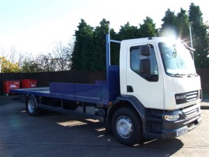
Posted on

DAF LF45, LF55 2001-2015 Workshop Repair & Service Manual (COMPLETE & INFORMATIVE for DIY REPAIR) ☆ ☆ ☆ ☆ ☆

DAF LF45, LF55 2001-2015 Workshop Repair & Service Manual (COMPLETE & INFORMATIVE for DIY REPAIR)

DAF LF45, LF55 2001-2015 Workshop Repair & Service Manual (COMPLETE & INFORMATIVE for DIY REPAIR) ☆ ☆ ☆ ☆ ☆

MDAFLF0115OPES.PDF
Price: $19.99 USD

* COMPLETE, Absolutely No Missing Pages!
* Official Service INFORMATION You Can Count On!
* Customer Satisfaction GUARANTEED!

This high QUALITY official manual for DAF LF45, LF55 2001-2015 is 100 percents COMPLETE and INTACT, no MISSING, CORRUPT pages, sections to freak you out! This manual is exactly as described. It is in the cross-platform PDF document format so that it works like a charm on all kinds of devices.

FORMAT: PDF
LANGUAGE: English
SIZE/PAGE: 185 MB
OS: Windows/Mac OS X/Linux/Android/iOS

MAKE: DAF
MODEL: LF45, LF55 Series
YEAR: 2001 2002 2003 2004 2005 2006 2007 2008 2009 2010 2011 2012 2013 2014 2015

DAF 2001 2002 2003 2004 2005 2006 2007 2008 2009 2010 2011 2012 2013 2014 2015 LF45-55, LF55 SERIES TRUCK

INSTANT DELIVERY: A download link will be sent to you instantly after payment. Simply click on the link and save it to your computer. You can use this Manual as long as you wish with no restrictions.

CUSTOMER SATISFACTION: If there is ANY kind of problem with the item you purchased, just drop a quick email. Within HOURS the issue shall be taken care of.

PRINTABLE MANUAL WITH DIAGRAMS: Just print the manual out and start to work. You can also use the manual with your Tablet/Laptop in your garage.

REFUND/EXCHANGE POLICY: We sell high QUALITY products only. However if you encounter any problems with the item you purchased, another replacement link will be sent to you. If we’re at fault, you will get 100 percents refund.

Buy ☆THE BEST MANUAL ON THE INTERNET☆ from responsible seller and get instant download now without uncertainty or surprise.

This highly detailed workshop service repair manual for download contains virtually everything you will ever need to repair, maintain, rebuild, refurbish or restore DAF LF45-55 2001-2015. All diagnostic and repair procedures and gives you access to the same information that professional technicians and mechanics have. You can view and print out the complete repair procedures with this workshop service repair manual Download – you do not need to be skilled with a computer.

MDAFLF0115OPES.PDF
Price: $19.99 USD

DAF LF45, LF55 2001-2015 Workshop Repair & Service Manual (COMPLETE & INFORMATIVE for DIY REPAIR) ☆ ☆ ☆ ☆ ☆

EXCERPTS:
3. THREADED CONNECTIONS
3.1 DIPPED THREADED CONNECTIONS
The components may have threaded connections that have been treated with lubricant (dipped threaded connection). Galvanized bolts and nuts are wax dipped in the factory. Black annealed and phosphatised bolts and nuts are oil dipped.
The advantage of using a lubricant is that friction during tightening of the threaded connection is reduced, so that the specified pre-tension can be obtained accurately and more easily. The tightening torque can be reduced while the pretension force remains the same.
To achieve a small spread in the pre-tension force, the dipped threaded connection must be tightened accurately. Therefore, always use a reliable torque wrench that provides a high degree of accuracy.
Note:
Have torque wrenches regularly inspected and calibrated.
To achieve the correct pre-tension when re-using nuts and bolts, it is important to clean the thread thoroughly. After cleaning, apply one drop of lubricant to the first turn of the screw thread and one drop to the contact surface of the nut or bolt.
If bolts and nuts are to be re-used, do not lubricate them with anything other than engine oil.
Lubricants other than engine oil or factory-applied lubricant must not be used under any
circumstances because of the difference in friction coefficient.
When locking compounds are used for dipped threaded connections, the instructions given here
apply, except for applying lubricant to the first turn of the screw thread.
The reason for this is that the friction coefficients of other lubricants vary too much and are not the same as those of the above-mentioned lubricants.
The use of locking compounds in combination with dipped bolts and nuts creates no problems.

4.1 DISASSEMBLY AND ASSEMBLY, AIR COMPRESSOR DRIVE GEAR
Disassembly, air compressor drive gear
1. Remove the air compressor.
2. Position a filter belt with a textile or leather band (usually used for removing screwed filters) around the drive gear.
3. Loosen the central attachment nut, using the filter pliers to prevent the air compressor shaft from turning along.
4. Remove the central attachment nut.
5. Use a puller to remove the drive gear.

Assembly, air compressor drive gear
1. Thoroughly clean the parts to be assembled.
The contact surfaces of the gear attachment and the air compressor shaft should be absolutely free from grease.
2. Inspect the parts to be assembled for damage and deformation. Replace the parts if necessary.
3. Fit the drive gear to the air compressor shaft.
4. Fit the central attachment nut to the air compressor shaft. Hold the air compressor gear in place using the filter belt. For the specified torque, see ‘Technical data’.
5. Fit the air compressor.

Posted on

DAF CF 1996-2012 Workshop Repair & Service Manual (COMPLETE & INFORMATIVE for DIY REPAIR) ☆ ☆ ☆ ☆ ☆

DAF CF 1996-2012 Workshop Repair & Service Manual (COMPLETE & INFORMATIVE for DIY REPAIR)
MDAFCF9612OPES.PDF
Price: $19.99 USD

DAF CF 1996-2012 Workshop Repair & Service Manual (COMPLETE & INFORMATIVE for DIY REPAIR) ☆ ☆ ☆ ☆ ☆

* COMPLETE, Absolutely No Missing Pages!
* Official Service INFORMATION You Can Count On!
* Customer Satisfaction GUARANTEED!

This high QUALITY official manual for DAF CF 1996-2012 is 100 percents COMPLETE and INTACT, no MISSING, CORRUPT pages, sections to freak you out! This manual is exactly as described. It is in the cross-platform PDF document format so that it works like a charm on all kinds of devices.

FORMAT: PDF
LANGUAGE: English
SIZE/PAGE: 272 MB
OS: Windows/Mac OS X/Linux/Android/iOS

MAKE: DAF
MODEL: CF65, CF75, CF85
YEAR: 1997 1998 1999 2000 2001 2002 2003 2004 2005 2006 2007 2008 2009 2010 2011 2012

INSTANT DELIVERY: A download link will be sent to you instantly after payment. Simply click on the link and save it to your computer. You can use this Manual as long as you wish with no restrictions.

CUSTOMER SATISFACTION: If there is ANY kind of problem with the item you purchased, just drop a quick email. Within HOURS the issue shall be taken care of.

PRINTABLE MANUAL WITH DIAGRAMS: Just print the manual out and start to work. You can also use the manual with your Tablet/Laptop in your garage.

REFUND/EXCHANGE POLICY: We sell high QUALITY products only. However if you encounter any problems with the item you purchased, another replacement link will be sent to you. If we’re at fault, you will get 100 percents refund.

Buy ☆THE BEST MANUAL ON THE INTERNET☆ from responsible seller and get instant download now without uncertainty or surprise.

This highly detailed workshop service repair manual for download contains virtually everything you will ever need to repair, maintain, rebuild, refurbish or restore DAF CF 1996-2012. All diagnostic and repair procedures and gives you access to the same information that professional technicians and mechanics have. You can view and print out the complete repair procedures with this workshop service repair manual Download – you do not need to be skilled with a computer.

Factory repair manuals are the same manuals as those used by the dealers. As they are primarily intended for dealer use the manufacturers usually release a base repair manual when a new model is introduced (either a single manual, multi-volume set or separate volumes) and then release supplementary manuals as the model changes, for example a model facelift or introduction of a new engine. Supplements generally cover only changes to the model and are intended to be used in conjunction with the base repair manual(s). For full coverage you will need the base repair manual and all relevant supplements up to the date your model was manufactured. Please note that workshop manuals are usually written for models sold in a specific country. Differences in specification can exist between models sold in different countries and items such as engines can vary.

MDAFCF9612OPES.PDF
Price: $19.99 USD

DAF CF 1996-2012 Workshop Repair & Service Manual (COMPLETE & INFORMATIVE for DIY REPAIR) ☆ ☆ ☆ ☆ ☆

EXCERPTS:
3.3 VISCOUS FAN CLUTCH
The fan is connected to the engine by means of a viscous fan clutch. If, under certain circumstances, the heat is not sufficiently dissipated by the air flow passing through the radiator, the fan will have to draw in extra cooling air through the radiator. In a viscous fan clutch, the drive torque is transmitted by a silicone fluid.
The fan clutch is divided into two chambers. In the working area (1) is the rotor (2), which is connected to the drive flange (7). The supply chamber (3) rotates freely round the drive flange
(7) and is connected to the fan. There is silicone fluid in the supply chamber (3). The opening (4) in the supply chamber (3) is closed by a valve (5).
The valve (5) is operated by a bimetallic strip (6). If the opening (4) in the supply chamber (3) is closed by the valve (5), no silicone fluid can enter the working area (1). The silicone fluid still present in the working area (1) will flow back to the supply chamber (3) through the bores (8). As only very little fluid will be left in the working area (1), there will be a great difference in rotating speed (slip) between the drive flange (7) and the supply chamber (3) with the fan.
When the air temperature increases, the bimetallic strip (6) will bend and the valve (5) will partially release the opening (4) in the supply chamber (3). Through this opening, a limited amount of silicone fluid can enter the working area (1) and flow past the rotor (2). This will cause friction, so that the difference in rotating speed (slip) between the drive flange (7) and the supply chamber (3) with the fan will decrease.
(6) will continue to bend and the opening (4) in the supply chamber (3) will be fully released. The further the opening (4) in the supply chamber (3) is released, the more silicone fluid will flow into the working area (1) and past the rotor (2). As a result of the increase in friction, the difference in rotating speed (slip) between the drive flange (7) and the supply chamber (3) will further decrease.

4.2 REMOVAL AND INSTALLATION, OIL COOLER
Removing the oil cooler
1. Drain the coolant. See ’Draining and filling’.
2. Remove the lubricating oil filter.
3. Remove the turbocharger oil supply pipe.
4. Remove the attachment bolts from the oil cooler and remove the oil cooler.
Installing the oil cooler
1. Fit the oil cooler with new gaskets and tighten the attachment bolts to the specified torque and in the specified sequence. See ’Technical data’.
2. Tighten the oil supply pipe to the specified torque. See ’Technical data’.
3. Fit the lubricating oil filter.
4. Fill the cooling system.
5. Run the engine briefly, and check that the oil cooler does not leak.
6. Check the lubricating oil level.
7. Check the coolant level.

Posted on

Daewoo Tico 1991-1996 Workshop Repair & Service Manual (COMPLETE & INFORMATIVE for DIY REPAIR) ☆ ☆ ☆ ☆ ☆

Daewoo Tico 1991-1996 Workshop Repair & Service Manual (COMPLETE & INFORMATIVE for DIY REPAIR)

MDWTC9196OPES.PDF
Price: $9.99 USD

Daewoo Tico 1991-1996 Workshop Repair & Service Manual (COMPLETE & INFORMATIVE for DIY REPAIR) ☆ ☆ ☆ ☆ ☆

* COMPLETE, Absolutely No Missing Pages!
* Official Service INFORMATION You Can Count On!
* Customer Satisfaction GUARANTEED!

This high QUALITY official manual for Daewoo Tico 1991-1996 is 100 percents COMPLETE and INTACT, no MISSING, CORRUPT pages, sections to freak you out! This manual is exactly as described. It is in the cross-platform PDF document format so that it works like a charm on all kinds of devices.

FORMAT: PDF
LANGUAGE: English
SIZE/PAGE: 86 MB
OS: Windows/Mac OS X/Linux/Android/iOS

INSTANT DELIVERY: A download link will be sent to you instantly after payment. Simply click on the link and save it to your computer. You can use this Manual as long as you wish with no restrictions.

CUSTOMER SATISFACTION: If there is ANY kind of problem with the item you purchased, just drop a quick email. Within HOURS the issue shall be taken care of.

PRINTABLE MANUAL WITH DIAGRAMS: Just print the manual out and start to work. You can also use the manual with your Tablet/Laptop in your garage.

REFUND/EXCHANGE POLICY: We sell high QUALITY products only. However if you encounter any problems with the item you purchased, another replacement link will be sent to you. If we’re at fault, you will get 100 percents refund.

Buy ☆THE BEST MANUAL ON THE INTERNET☆ from responsible seller and get instant download now without uncertainty or surprise.

This highly detailed workshop service repair manual for download contains virtually everything you will ever need to repair, maintain, rebuild, refurbish or restore Daewoo Tico 1991 1992 1993 1994 1995 1996. All diagnostic and repair procedures and gives you access to the same information that professional technicians and mechanics have. You can view and print out the complete repair procedures with this workshop service repair manual Download – you do not need to be skilled with a computer.

Factory repair manuals are the same manuals as those used by the dealers. As they are primarily intended for dealer use the manufacturers usually release a base repair manual when a new model is introduced (either a single manual, multi-volume set or separate volumes) and then release supplementary manuals as the model changes, for example a model facelift or introduction of a new engine. Supplements generally cover only changes to the model and are intended to be used in conjunction with the base repair manual(s). For full coverage you will need the base repair manual and all relevant supplements up to the date your model was manufactured. Please note that workshop manuals are usually written for models sold in a specific country. Differences in specification can exist between models sold in different countries and items such as engines can vary.

Daewoo Tico 1991 1992 1993 1994 1995 1996


MDWTC9196OPES.PDF
Price: $9.99 USD

KEY WORDS:
General Information, Specifications, Lube Points, Oil Types, Periodic Maintenance and Tune-Up Procedures, Engine Servicing, Disassembly, Reassembly, Engine Removal, Fuel and Lubrication Systems, Carb Rebuild, Carb Adjustments, Electrical System, Ignition, Charging, Starter, Battery, Switches, Chassis, Wheels, Brakes, Steering, Suspension, Axles, Chassis Assembly, Servicing Information, Wiring Diagrams, Wire/Cable/Hose Routing, Tools, Tightening Torques, Service Data, Complete Engine Service, Fuel System Service, All Factory Repair Procedures, Wiring Diagrams, Gearbox, Exhaust System, Suspension, Fault Finding, Clutch Removal and Installation, Front Suspension, Bodywork, Gearbox Service, Gearbox Removal and Installation, Cooling System, Detailed Specifications, Transmission, Factory Maintenance Schedules, Electrics, Engine Firing Order, Brake Servicing Procedures, U-Joint Service Procedures, CV Joint Service Procedures, Timing Chain Service, Exhaust Service, Abundant Illustrations, Lots of pictures & diagrams, Plus Lots More.

Posted on

Daewoo Nubira/Lacetti 2004 Workshop Repair & Service Manual (COMPLETE & INFORMATIVE for DIY REPAIR)

Daewoo Nubira/Lacetti 2004 Workshop Repair & Service Manual (COMPLETE & INFORMATIVE for DIY REPAIR)

MDWNL04OPEK
Price: $12.99 USD

Daewoo Nubira/Lacetti 2004 Workshop Repair & Service Manual (COMPLETE & INFORMATIVE for DIY REPAIR) ☆ ☆ ☆ ☆ ☆

* COMPLETE, Absolutely No Missing Pages!
* Official Service INFORMATION You Can Count On!
* Customer Satisfaction GUARANTEED!

This high QUALITY official manual for Daewoo Nubira/Lacetti 2004 is 100 percents COMPLETE and INTACT, no MISSING, CORRUPT pages, sections to freak you out! This manual is exactly as described. It is in the cross-platform PDF document format so that it works like a charm on all kinds of devices.

FORMAT: PDF/HTML etc.
LANGUAGE: English
SIZE/PAGE: 116 MB
OS: Windows/Mac OS X/Linux/Android/iOS

INSTANT DELIVERY: A download link will be sent to you instantly after payment. Simply click on the link and save it to your computer. You can use this Manual as long as you wish with no restrictions.

CUSTOMER SATISFACTION: If there is ANY kind of problem with the item you purchased, just drop a quick email. Within HOURS the issue shall be taken care of.

PRINTABLE MANUAL WITH DIAGRAMS: Just print the manual out and start to work. You can also use the manual with your Tablet/Laptop in your garage.

REFUND/EXCHANGE POLICY: We sell high QUALITY products only. However if you encounter any problems with the item you purchased, another replacement link will be sent to you. If we’re at fault, you will get 100 percents refund.

Buy ☆THE BEST MANUAL ON THE INTERNET☆ from responsible seller and get instant download now without uncertainty or surprise.

This highly detailed workshop service repair manual for download contains virtually everything you will ever need to repair, maintain, rebuild, refurbish or restore Daewoo Nubira/Lacetti 2004. All diagnostic and repair procedures and gives you access to the same information that professional technicians and mechanics have. You can view and print out the complete repair procedures with this workshop service repair manual Download – you do not need to be skilled with a computer.

Factory repair manuals are the same manuals as those used by the dealers. As they are primarily intended for dealer use the manufacturers usually release a base repair manual when a new model is introduced (either a single manual, multi-volume set or separate volumes) and then release supplementary manuals as the model changes, for example a model facelift or introduction of a new engine. Supplements generally cover only changes to the model and are intended to be used in conjunction with the base repair manual(s). For full coverage you will need the base repair manual and all relevant supplements up to the date your model was manufactured. Please note that workshop manuals are usually written for models sold in a specific country. Differences in specification can exist between models sold in different countries and items such as engines can vary.


MDWNL04OPEK
Price: $12.99 USD

EXCERPTS:
MAINTENANCE AND REPAIR
ON–VEHICLE SERVICE
ENGINE COVER
Removal Procedure
1. Remove the bolts and nuts from the engine cover.
2. Remove the engine cover.
Installation Procedure
1. Position the engine cover on the engine.
2. Install the engine cover bolts and nuts.
Tighten
Tighten the engine cover bolts and nuts to 10 NSm(89 lb–ft).
CAMSHAFT COVER
Removal Procedure
1. Disconnect the negative battery cable.
2. Remove the engine cover. Refer to ”Engine” in this section.
3. Remove the breather hose, ventilation hose and cam position sensor wiring connector from the camshaft cover.
4. Remove the ignition wires from the spark plug.
5. Remove the camshaft cover bolts and camshaft cover.
6. Remove the camshaft cover gasket.
Installation Procedure
1. Install the camshaft cover gasket on the camshaft cover.
2. Position the camshaft cover on the engine block.
3. Install the camshaft cover bolts.
Tighten
Tighten the camshaft cover bolts to 10 NSm (89 lb–ft).
4. Install the ignition wires to the spark plugs and connect the breather hose, ventilation hose and cam position sensor wiring connector to the can-shaft cover.
5. Install the engine cover.
6. Connect the negative battery cable.
INTAKE MANIFOLD
Removal Procedure
1. Remove the fuel pump fuse.
2. Start the engine. After it stalls, crank the engine for 10 seconds to rid the fuel system of fuel pressure.
3. Disconnect the negative battery cable.
4. Drain the engine coolant. Refer to Section 1D, Engine Cooling.
5. Remove the engine cover and throttle body. Refer to Section 1F, Engine Control.
Installation Procedure
1. Install the rear timing belt cover.
2. Install the rear timing belt cover bolts.
Tighten
Tighten the rear timing belt cover bolts to 10 NSm (89 lb–in).
3. Install the timing belt idler pulley.
4. Install the timing belt idler pulley bolt.
Tighten
Tighten the timing belt idler pulley bolt to 40 NSm (30 lb–ft).
5. Install the timing belt automatic tensioner.
6. Install the timing belt automatic tensioner bolts.
Tighten
Tighten the timing belt automatic tensioner bolts to 25 NSm (18 lb–ft).
7. Install the crankshaft gear.
Notice : Take extreme care to prevent any scratches, nicks or damage to the camshafts.
8. Install the camshaft gears. Refer to ”Camshaft Gears” in this section.
9. Install the timing belt and timing belt cover. Refer to ”Timing Belt” in this section.
ENGINE
Removal Procedure
1. Remove the fuel pump fuse.
2. Start the engine. After it stalls, crank the engine for 10 seconds to rid the fuel system of fuel pressure.
3. Remove the hood. Refer to Section 9R, Body Front End.
4. Drain the engine oil.
5. Disconnect the negative battery cable.
6. Remove the air cleaner outlet hose from the throttle body and air cleaner housing.
7. Disconnect the breather tubes from the camshaft cover.
8. Remove the serpentine accessory drive belt. Refer to Section 6B, Power Steering Pump.
9. Remove the right front wheel. Refer to Section 2E, Tires and Wheels.
10. Remove the right front wheel well splash shield.
11. Drain the engine coolant. Refer to Section 1D, Engine Cooling.
12. Remove the cooling system radiator and the engine cooling fans. Refer to Section 1D, Engine Cooling.
13. Disconnect the upper radiator hose from the thermostat housing.
14. Disconnect the power steering return hose from the power steering pump. Refer to Section 6A, Power Steering System.
15. Disconnect the power steering pressure hose from the power steering pump. Refer to Section 6A, Power Steering System.
16. Disconnect the electrical connector at the direct ignition system (DIS) coil and the electronic control module (ECM) ground terminal at the intake manifold and at the starter motor.