Posted on

Caterpillar 3114, 3116 and 3126 Engines Factory Service & Shop Manual


Download Link

INSTANT DOWNLOAD


Complete workshop & service manual with electrical wiring diagrams for Caterpillar 3114, 3116, 3126 Diesel Engines. It’s the same service manual used by dealers that guaranteed to be fully functional and intact without any missing page.

This Caterpillar 3114, 3116 and 3126 Diesel Engines service & repair manual (including maintenance, overhaul, disassembling & assembling, adjustment, tune-up, operation, inspecting, diagnostic & troubleshooting…) is divided into different sections. Each section covers a specific component or system with detailed illustrations. A table of contents is placed at the beginning of each section. Pages are easily found by category, and each page is expandable for great detail. The printer-ready PDF documents work like a charm on all kinds of devices.

MANUAL LIST:
KENR9511 – Schematic – Marine Multi-Station Control System II Electrical System – Typical Dual Engine Installation
RENR1377 – Systems Operation (Electric Protection System Energize-To-Run for Generator Set, Industrial & Marine Diesel Engines)
RENR1377 – Testing & Adjusting (Electric Protection System Energize-To-Run for Generator Set, Industrial & Marine Diesel Engines)
RENR7651 – Systems Operation (Marine Multi-Station Control System)
RENR7651 – Testing & Adjusting (Marine Multi-Station Control System)
RENR7651 – Troubleshooting (Marine Multi-Station Control System)
RENR7893 – Marine Multi-Station Control System Electrical System – Typical Single Engine Installation
RENR7893 – Schematic – Marine Multi-Station Control System Electrical System – Typical Single Engine Installation
RENR7929 – Schematic – Marine Multi-Station Control System Electrical System – Typical Dual Engine Installation
SEGV3008 – Systems Operation (Fundamentals Electrical System for All Caterpillar Products)
SENR3581 – Disassembly & Assembly (37-MT, 41-MT, 42-MT Series Starting Motors)
SENR3581 – Systems Operation (37-MT, 41-MT, 42-MT Series Starting Motors)
SENR3581 – Testing & Adjusting (37-MT, 41-MT, 42-MT Series Starting Motors)
SENR3581 – Troubleshooting (37-MT, 41-MT, 42-MT Series Starting Motors)
SENR3947 – Disassembly & Assembly (Supplement for 3116 & 3126 Marine Engine)
SENR3947 – Specifications (Supplement for 3116 & 3126 Marine Engine)
SENR3981 – Schematic – Fluid Power & Electrical Graphic Symbols
SENR3981 – Schematic – Fluid Power and Electrical Graphic Symbols
SENR4695 – Disassembly & Assembly (Model MG 5050 Marine Transmission)
SENR6454 – Disassembly and Assembly (3114, 3116 and 3126 MUI Engine Governors)
SENR6454 – Specifications (3114, 3116 and 3126 MUI Engine Governors)
SENR6454 – Systems Operation (3114, 3116 and 3126 MUI Engine Governors)
SENR6454 – Testing and Adjusting (3114, 3116 and 3126 MUI Engine Governors)
SENR6502 – Troubleshooting (3114, 3116 & 3126 Engines)
SENR7508 – Disassembly & Assembly (30SI Series & 34SI Series Alternator)
SENR7508 – Systems Operation (30SI Series & 34SI Series Alternator)
SENR7508 – Testing & Adjusting (30SI Series & 34SI Series Alternator)
SENR9518 – Disassembly and Assembly (3114, 3116 & 3126 Engines)
SENR9557 – Specifications (3114, 3116 & 3126 Industrial, Marine & Generator Set Engines)
SENR9558 – Systems Operation (3114, 3116 & 3126 Industrial, Marine & Generator Set Engines)
SENR9558 – Testing & Adjusting (3114, 3116 & 3126 Industrial, Marine & Generator Set Engines)
SENR3581 – Specifications (37-MT, 41-MT, 42-MT Series Starting Motors).pdf
SENR3947 – Systems Operation (Supplement for 3116 & 3126 Marine Engine).pdf
SENR3947 – Testing & Adjusting (Supplement for 3116 & 3126 Marine Engine).pdf
SENR4695 – General Service Information – Marine Transmission (Model MG 5050 Marine Transmission).pdf
SENR4695 – Systems Operation (Model MG 5050 Marine Transmission).pdf
SENR4695 – Troubleshooting – Introduction (Model MG 5050 Marine Transmission).pdf
SENR7508 – Specifications (30SI Series & 34SI Series Alternator).pdf
SENR3130 – Torque Specifications
UENR3262 – Disassembly & Assembly – Seal Installation
1. CATERPILLAR – 3116 – FUEL SYSTEM – DIESEL -1994 GMC C Series – C7.pdf
2. CATERPILLAR – 3116 -1994 GMC C Series – C7.pdf
SEBF9050 – Applied Failure Analysis – Engine Valve Failure Modes{1100, 1105}.pdf
SEBU6875 – Owner’s Manual (Caterpillar Driver Information Display).pdf
SENR2995 – Product Safety.pdf
SENR3130 – Specifications (Torque Specifications for All Caterpillar Products).pdf

EXCERPT:
b. Install servo valve (72) into servo piston (71) .
c. Install O-ring seal (75) onto sleeve (70) and slide the sleeve onto servo piston (71) .
d. Install a new 109-4587 Tolerance Ring (76) into the large bore in the end of servo piston (71). Position the tolerance ring so that the gap in the tolerance ring lines up with the hole through the side of the piston that is for spring pin (74). Push the tolerance ring into the bore until the tolerance ring bottoms out.

Posted on

Caterpillar 3064 & 3066 Engines Factory Service & Shop Manual


Download Link

INSTANT DOWNLOAD


Complete workshop & service manual with electrical wiring diagrams for Caterpillar 3064 & 3066 Engines. It’s the same service manual used by dealers that guaranteed to be fully functional and intact without any missing page.

This Caterpillar 3064 & 3066 Diesel Engines service & repair manual (including maintenance, overhaul, disassembling & assembling, adjustment, tune-up, operation, inspecting, diagnostic & troubleshooting…) is divided into different sections. Each section covers a specific component or system with detailed illustrations. A table of contents is placed at the beginning of each section. Pages are easily found by category, and each page is expandable for great detail. The printer-ready PDF documents work like a charm on all kinds of devices.

MANUAL LIST:
SENR5553 – Disassembly & Assembly (3064 & 3066 Engines for Caterpillar Built Machines)
SENR5545 – Specifications (3064 & 3066 Engines for Caterpillar Built Machines)
SENR5546 – Systems Operation (3064 & 3066 Engines for Caterpillar Built Machines)
SENR5546 – Testing & Adjusting (3064 & 3066 Engines for Caterpillar Built Machines)

EXCERPT:
Installation Procedure
NOTICE
Keep all parts clean from contaminants. Contaminants may cause rapid wear and shortened component life. Place the fuel return line (10) in position on the engine. Connect fitting (9) of the fuel return line to the fuel injection pump.
1.
Install the washer and bolt (8) through the clamp in order to secure the fuel return line to the inlet manifold.
2.
Install the fuel return line (10) to the fuel injection nozzles. Secure the fuel return line to the fuel injection nozzle with acorn nuts (7) .

Posted on

Caterpillar 3056E Engine Factory Service & Shop Manual


Download Link

INSTANT DOWNLOAD


Complete workshop & service manual with electrical wiring diagrams for Caterpillar 3056E Diesel Engine. It’s the same service manual used by dealers that guaranteed to be fully functional and intact without any missing page.

This Caterpillar 3056E Engine service & repair manual (including maintenance, overhaul, disassembling & assembling, adjustment, tune-up, operation, inspecting, diagnostic & troubleshooting…) is divided into different sections. Each section covers a specific component or system with detailed illustrations. A table of contents is placed at the beginning of each section. Pages are easily found by category, and each page is expandable for great detail. The printer-ready PDF documents work like a charm on all kinds of devices.

MANUAL LIST:
RENR2417 – Troubleshooting (3054E & 3056E Industrial Engines and Engines for Caterpillar Built Machines)
RENR2400 – Disassembly and Assembly (3056E Engine for Caterpillar Built Machines)
RENR2401 – Specifications (3056E Engine for Caterpillar Built Machines)
RENR2416 – Systems Operation (3056E Engines for Caterpillar Built Machines)
RENR2416 – Testing & Adjusting (3056E Engines for Caterpillar Built Machines)

EXCERPT:
3. rear seal into the housing.
4. Lubricate the components with clean engine oil. Install Tooling (A) onto the crankshaft flange.
5. Position the new gasket on the dowels in the cylinder block.
Typical example
6. Place housing (3) and crankshaft rear seal (4) over Tooling (A).
7. Position housing (3) on the dowels in the cylinder block.
8. Remove Tooling (A).

Posted on

Caterpillar 3003, 3013, 3014 and 3024 Diesel Engines Factory Service & Shop Manual


Download Link

INSTANT DOWNLOAD


Complete workshop & service manual with electrical wiring diagrams for Caterpillar 3003, 3013, 3014 and 3024 Diesel Engines. It’s the same service manual used by dealers that guaranteed to be fully functional and intact without any missing page.

This Caterpillar 3003, 3013, 3014 and 3024 Diesel Engines service & repair manual (including maintenance, overhaul, disassembling & assembling, adjustment, tune-up, operation, inspecting, diagnostic & troubleshooting…) is divided into different sections. Each section covers a specific component or system with detailed illustrations. A table of contents is placed at the beginning of each section. Pages are easily found by category, and each page is expandable for great detail. The printer-ready PDF documents work like a charm on all kinds of devices.

MANUAL LIST:
SENR5022 – Specifications (3003, 3013, 3014 and 3024 Engines for Caterpillar Built Machines)
SENR5023 – Systems Operation (3003, 3013, 3014 and 3024 Engines for Caterpillar Built Machines)
SENR5023 – Testing & Adjusting (3003, 3013, 3014 and 3024 Engines for Caterpillar Built Machines)
SENR5027 – Disassembly & Assembly (3003, 3013, 3014 and 3024 Engines for Caterpillar Built Machines)

EXCERPT:
1. Align flywheel housing (6) on the dowels that
2. are on the rear of the cylinder block.
3. Install four nuts and four bolts (5) that fasten the backplate to flywheel housing (6) .

Posted on

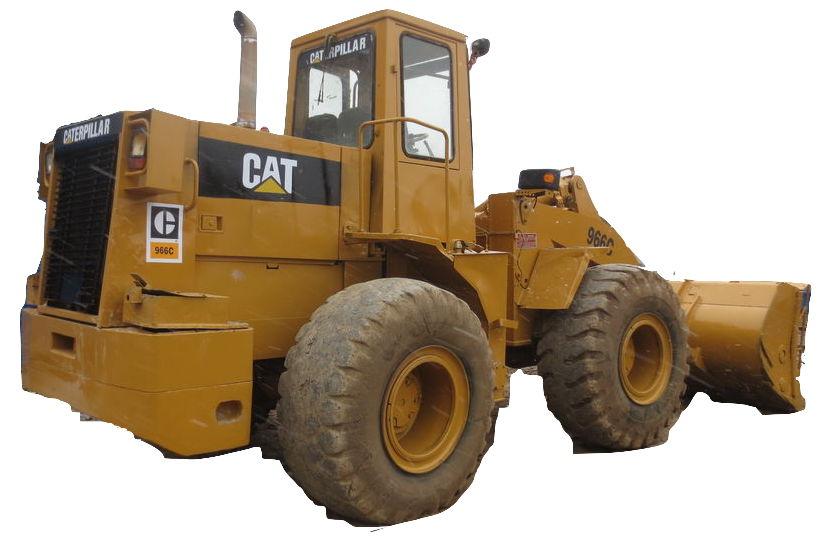
Caterpillar 966 & 966C Wheel Loaders Factory Service & Shop Manual


Download Link

INSTANT DOWNLOAD


Complete workshop & service manual with electrical wiring diagrams for Caterpillar 966 & 966C Wheel Loaders. It’s the same service manual used by dealers that guaranteed to be fully functional and intact without any missing page.

This Caterpillar 966 & 966C Wheel Loaders service & repair manual (including maintenance, overhaul, disassembling & assembling, adjustment, tune-up, operation, inspecting, diagnostic & troubleshooting…) is divided into different sections. Each section covers a specific component or system with detailed illustrations. A table of contents is placed at the beginning of each section. Pages are easily found by category, and each page is expandable for great detail. The printer-ready PDF documents work like a charm on all kinds of devices.

MANUAL LIST:
REG01117 – Disassembly & Assembly (966 Wheel Loader Power Train)
REG01118 – Disassembly & Assembly (966 Wheel Loader Vehicle Systems)
REG01415 – Specifications (966 Wheel Loader Air System & Brakes)
REG01432 – Specifications (966 Wheel Loader Steering System)
REG01437 – Specifications (966 Wheel Loader Power Train)
REG01514 – Specifications (966C Wheel Loader Hydraulic System)
SENR2055 – Disassembly and Assembly (950 & 966C Wheel Loaders Operator’s Station)
SENR5229 – Disassembly and Assembly (Supplement 966C Wheel Loader Transmission)
REG00684 – Disassembly and Assembly (General Instructions).pdf
REG01112 – Systems Operation (966 Wheel Loader Power Train).pdf
REG01112 – Testing & Adjusting (966 Wheel Loader Power Train).pdf
REG01113 – Systems Operation (966 Wheel Loader Steering System).pdf
REG01113 – Testing & Adjusting (966 Wheel Loader Steering System).pdf
REG01114 – Systems Operation (966 Wheel Loader Air System And Brakes).pdf
REG01114 – Testing & Adjusting (966 Wheel Loader Air System And Brakes).pdf
REG01115 – Systems Operation (966 Wheel Loader Hydraulic System).pdf
REG01115 – Testing and Adjusting (966 Wheel Loader Hydraulic System).pdf
REG01248 – Testing & Adjusting (950 & 966 Power Shift Transmission).pdf

EXCERPT:
Wheel Bearing Adjustment
FINAL DRIVE
1. Retainer nut. 2. Wheel. 3. Bearings. 4. Wheel stud.
1. Put an 8.00 in. (203.2 mm) torque wrench on wheel stud (4).
2. Tighten nut (1) while turning wheel (2) to a torque of 160 ± 50 lb. in. (184.5 ± 57.7 cm.kg). This torque reading must be held through one complete revolution of wheel (2). If necessary, do the procedure again to get the correct torque.
3. After getting the correct preload on bearings (3), loosen nut (1). Again, tighten nut (1) while turning wheel (2) to a torque of 75 ± 25 lb. in. (86.5 ± 28.8 cm.kg) for one complete revolution.
4. Turn the nut to the next groove and lock in place.