Posted on

Caterpillar 3508C/3512C/3516C Engines Factory Service & Shop Manual + Parts Manual


Download Link

INSTANT DOWNLOAD (add to cart)


Complete workshop & service manual with electrical wiring diagrams for Caterpillar 3508C/3512C/3516C Generator Set / Industrial / Machine / Marine / Petroleum Engines. It’s the same service manual used by dealers that guaranteed to be fully functional and intact without any missing page.

This Caterpillar 3508C/3512C/3516C Generator Set / Industrial / Machine / Marine / Petroleum Engines service & repair manual (including maintenance, overhaul, disassembling & assembling, adjustment, tune-up, operation, inspecting, diagnostic & troubleshooting…) is divided into different sections. Each section covers a specific component or system with detailed illustrations. A table of contents is placed at the beginning of each section. Pages are easily found by category, and each page is expandable for great detail. The printer-ready PDF documents work like a charm on all kinds of devices.

MANUAL LIST:
SEBP4364 – Parts Manual (3512C Engine).pdf
KENR5402 – Specifications (3500C Marine Engines)
KENR5403 – Systems Operation (3500 Marine Engines)
KENR5403 – Testing & Adjusting (3500 Marine Engines)
KENR5405 – Troubleshooting (3500C Marine Auxiliary Engines)
KENR6055 – Disassembly & Assembly (3508C, 3512C, 3516C Marine Engines)
UENR4397 – Testing & Adjusting (3516C High Displacement Industrial Engine)
UENR0576 – Specifications (3516C Petroleum Engines)
UENR0577 – Systems Operation (3516C HD Petroleum Well Service Engines)
UENR0577 – Testing & Adjusting (3516C HD Petroleum Well Service Engines)
UENR0578 – Troubleshooting (3516C HD Petroleum Well Service Engines)
UENR2650 – Schematic (3516C Well Fracturing Engine Electrical System)
UENR3273 – Disassembly & Assembly (3516C Petroleum Engines)
UENR4397 – Systems Operation (3516C High Displacement Industrial Engine)
KENR5415 – Specifications (3512C & 3516C Industrial Engines)

EXCERPT:
Illustration 7
6. Use Tooling (E) and a suitable press to install rotating seal group (6). Rotating seal group (6) is to be installed with installation clips (X) in place until rotating seal group (6) is fully seated. Remove installation clips (X).
Note: Do not use hammer to install seal groups as damage to the ceramic faces on the seal groups will occur.
Illustration 8

7. Lubricate the shaft assembly with a light coat of engine oil. Use a suitable press to install impeller (5) into pump housing (10) and onto the shaft assembly. Install impeller (5) to a depth of 0.0 ± 0.15 mm (0.00000 ± 0.00591 inch) from the end of the shaft assembly to the outer face of the impeller.

Posted on

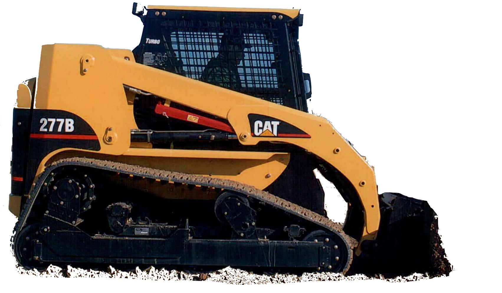
Caterpillar 267B, 277B, 287B Multi Terrain Loaders Factory Service & Shop Manual


Download Link

INSTANT DOWNLOAD (add to cart)


Complete workshop & service manual with electrical wiring diagrams for Caterpillar 267B, 277B, 287B Multi Terrain Loaders. It’s the same service manual used by dealers that guaranteed to be fully functional and intact without any missing page.

This Caterpillar 267B, 277B, 287B Multi Terrain Loaders service & repair manual (including maintenance, overhaul, disassembling & assembling, adjustment, tune-up, operation, inspecting, diagnostic & troubleshooting…) is divided into different sections. Each section covers a specific component or system with detailed illustrations. A table of contents is placed at the beginning of each section. Pages are easily found by category, and each page is expandable for great detail. The printer-ready PDF documents work like a charm on all kinds of devices.

MANUAL LIST:
RENR4883 – Disassembly & Assembly (267B, 277B, 287B Multi Terrain Loaders Engine Supplement)
RENR4884 – Disassembly & Assembly (267B, 277B & 287B Multi Terrain Loaders Power Train)
RENR4885 – Specifications (267B, 277B & 287B Multi Terrain Loaders Machine Systems)
RENR4886 – Systems Operation (267B, 277B & 287B Multi Terrain Loaders Machine Systems)
RENR4887 – Testing & Adjusting (267B, 277B & 287B Multi Terrain Loaders Machine Systems)
RENR4888 – Disassembly & Assembly (267B, 277B & 287B Multi Terrain Loaders Machine Systems)
RENR4889 – Schematic (247B, 247B2, 257B, 257B2, 267B, 277B, 287B Multi Terrain Loaders Hydraulic System)
RENR6417 – Systems Operation (247B, 257B, 267B, 277B & 287B Multi Terrain Loaders & 216B, 226B, 232B, 236B, 242B, 246B, 248B, 252B, 262B & 268B Skid Steer Loaders Interlock Electronic Control System)
RENR6417 – Testing & Adjusting (247B, 257B, 267B, 277B & 287B Multi Terrain Loaders & 216B, 226B, 232B, 236B, 242B, 246B, 248B, 252B, 262B & 268B Skid Steer Loaders Interlock Electronic Control System)
RENR6417 – Troubleshooting (247B, 257B, 267B, 277B & 287B Multi Terrain Loaders & 216B, 226B, 232B, 236B, 242B, 246B, 248B, 252B, 262B & 268B Skid Steer Loaders Interlock Electronic Control System)
RENR6418 – Systems Operation (247B, 257B, 267B, 277B, 287B Multi Terrain Loaders and 216B, 226B, 232B, 236B, 242B, 246B, 248B, 252B, 262B, 268B Skid Steer Loaders Auxiliary Hydraulic Electronic Control System)
RENR6418 – Testing & Adjusting (247B, 257B, 267B, 277B, 287B Multi Terrain Loaders and 216B, 226B, 232B, 236B, 242B, 246B, 248B, 252B, 262B, 268B Skid Steer Loaders Auxiliary Hydraulic Electronic Control System)
RENR6418 – Troubleshooting (247B, 257B, 267B, 277B, 287B Multi Terrain Loaders and 216B, 226B, 232B, 236B, 242B, 246B, 248B, 252B, 262B, 268B Skid Steer Loaders Auxiliary Hydraulic Electronic Control System)
RENR6419 – Schematic (Skid Steer Loaders_216B, 216B2, 226B, 226B2, 232B, 232B2, 236B, 236B2, 242B, 242B2, 246B, 248B, 252B, 252B2, 262B, 268B & Multi Terrain Loaders_247B, 247B2, 257B, 257B2, 267B, 277B, 287B Electrical System)
RENR8749 – Schematic (248B and 268B Skid Steer Loader 287B Multi Terrain Loader Hydraulic System)
RENR8751 – Schematic (247B, 247B2, 257B, 257B2, 267B, 277B, 287B Multi-Terrain Loader Hydraulic System)

EXCERPT:
3. spring (5) . Remove fitting (6).
Illustration 4
Typical Example
4. Install Tooling (H) . Use low pressure compressed air to remove piston (7) .
Note: Low-pressure air is required in order to allow the piston to release from the motor.
Note: Tooling (H) is required in order to prevent damage to the piston.
5. Remove O-ring seal (8) .