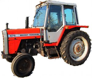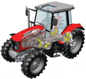
Posted on

Massey-Ferguson Tractor Series 5400 Factory Service & Shop Manual


Pages from AGCO-Massey-Ferguson Tractor Series 5400 (Model MF 5425-5435-5445-5455-5460-5460SA-5465-5470-5470SA-5475SA) Workshop Service Manual

MMF5400OPES.zip
Price: $29.99 USD

Complete workshop & service manual with electrical wiring diagrams for Massey-Ferguson Tractor Series 5400 (Model MF 5425, 5435, 5445, 5455, 5460, 5460SA, 5465, 5470, 5470SA, 5475SA). It’s the same service manual used by dealers that guaranteed to be fully functional and intact without any missing page.

This Massey-Ferguson Tractor Series 5400 (Model MF 5425/5435/5445/5455/5460/5460SA/5465/5470/5470SA/5475SA) service & repair manual (including maintenance, overhaul, disassembling & assembling, adjustment, tune-up, operation, inspecting, diagnostic & troubleshooting…) is divided into different sections. Each section covers a specific component or system with detailed illustrations. A table of contents is placed at the beginning of each section. Pages are easily found by category, and each page is expandable for great detail. The printer-ready PDF documents work like a charm on all kinds of devices.

FILELIST:
AGCO/Massey-Ferguson Tractor Series 5400 (Model MF 5425/5435/5445/5455/5460/5460SA/5465/5470/5470SA/5475SA) Workshop Service Manual.pdf
AGCO/Massey-Ferguson Tractor Series 5400 (Models 5425-5435-5445-5455-5460-5465) Operator Instruction Book.pdf

EXCERPT:
DANA – Differential
E . Removing the differential unit
10. Place the housing (7) in a vice fitted with soft jaws (Fig. 4).
11. Take out the screw (30) and its lock (31) (Fig. 4).
12. Take off the spline nut (32) using the special makeshift wrench (see § Q).
13. Take out the four screws (42).
14. Take off the half-bearings (43) (Fig. 4).
CAUTION: Take care not to release the spring (17) when releasing the differential lock half bearing. The washer (21) that seats the spring should stay in the housing.
15. Remove the differential assembly complete with cones (33) and cups (29) (Fig. 5). Separate the cups from the cones. Remove the shim(s) (22) used to
adjust the backlash.
NOTE: Pair up the bearing cones and cups in they are to be re-used.

Posted on

AGCO/Massey-Ferguson Tractor Series 3000/3100/3600 Factory Service & Shop Manual


Pages from AGCO-Massey-Ferguson Tractor Series 3600 (Model MF 3615-3625-3635-3645) Workshop Service Manual

MMF3000OPES.zip
Price: $29.99 USD

Complete workshop & service manual with electrical wiring diagrams for AGCO/Massey-Ferguson Tractor Series 3000/3100/3600 (3050, 3060, 3065, 3070, 3080, 3095, 3115, 3125, 3120, 3140, 3615, 3625, 3635, 3645). It’s the same service manual used by dealers that guaranteed to be fully functional and intact without any missing page.

This AGCO/Massey-Ferguson Tractor Series 3000/3100/3600 service & repair manual (including maintenance, overhaul, disassembling & assembling, adjustment, tune-up, operation, inspecting, diagnostic & troubleshooting…) is divided into different sections. Each section covers a specific component or system with detailed illustrations. A table of contents is placed at the beginning of each section. Pages are easily found by category, and each page is expandable for great detail. The printer-ready PDF documents work like a charm on all kinds of devices.

FILELIST:
1646915 M1 – AGCO/Massey-Ferguson Tractor Series 3000/3100 (Model MF 3050/3060/3065/3070/3080/3095/3115/3125/3120/3140) Workshop Service Manual.pdf
AGCO/Massey-Ferguson Tractor Series 3600 (Model MF 3615/3625/3635/3645) Workshop Service Manual.pdf

EXCERPT:
Hydraulic Lift
Section 2
Table of Contents
SPECIFICATIONS . . . 248
TECHNICAL FEATURES . . . 248
DIMENSIONAL FEATURES . . 248
CALIBRATION SETTINGS OF CONTROL VALVE . . . 248
DIAGRAM . . . 249
CIRCUIT DIAGRAM OF HYDRAULIC LIFTING DEVICE . . . 250
FUNCTIONING OF CONTROL VALVE . . 251
NEUTRAL PHASE . . 251
DELIVERY PHASE . . 252
DISCHARGE PHASE . . 253
HOW THE INTERNAL LEVERAGE SYSTEM FUNCTIONS . . 254
FUNCTIONING WITH POSITION CONTROL (FIG. PAGE 5.2) . . . 254
FUNCTIONING OF DRAFT CONTROL (FIG. PAGE 5.2 – 5.4) . . 256
COMBINED FUNCTIONING OF POSITION AND DRAFT CONTROL (FIG. PAGE 5.2-5.4) . . . 258
USE OF CONTROL LEVERS . . 259
POSITION CONTROL (LEVER 1) . . 259
DRAFT CONTROL (LEVER 2) . . . 259
COMBINED OPERATION FOR POSITION AND DRAFT CONTROL . . . 259
ADJUSTMENT OF CONTROL VALVE SENSITIVITY . . . 260
FUNCTIONING OF THE SENSITIVITY OF THE CONTROL VALVE . . . 260
ADJUSTMENT OF POSITION CONTROL LEVER . . . 262
ADJUSTMENT OF DRAFT CONTROL LEVER . . 263
CONTROL OF ASSEMBLY OF REACTION SPRING . . . 264
MEASUREMENT CONTROL OF PUSH ROD . . . 265
DIAGNOSTIC . . 266

Posted on

Massey-Ferguson MF 600-Series Factory Service & Shop Manual


Pages from 1856274 M1 – Massey-Ferguson MF 600 Series Workshop Service Manual

MMF600OPES.zip
Price: $29.99 USD

Complete workshop & service manual with electrical wiring diagrams for Massey-Ferguson MF 600-Series. It’s the same service manual used by dealers that guaranteed to be fully functional and intact without any missing page.

This Massey-Ferguson MF 600-Series service & repair manual (including maintenance, overhaul, disassembling & assembling, adjustment, tune-up, operation, inspecting, diagnostic & troubleshooting…) is divided into different sections. Each section covers a specific component or system with detailed illustrations. A table of contents is placed at the beginning of each section. Pages are easily found by category, and each page is expandable for great detail. The printer-ready PDF documents work like a charm on all kinds of devices.

1856274 M1 – Massey-Ferguson MF 600 Series Workshop Service Manual.pdf

EXCERPT:
CLUTCH RELEASE MECHANISM
GEARBOX TYPES A, B, C, D, E
Special Tools: MS 2700 Rail Trolley
Removal 58-04–11
1. Split the tractor between the engine and the transmission, Part 3A.
2. Remove the two springs.
3. Slide the carrier and release bearing off the input housing.
4. Remove the locking wire and locking peg.
5. Remove the circlip.
6. Remove the shaft.
7. Remove the clutch release fork.
8. Press the release bearing off the carrier.
Refitment
9. Reverse procedures 1 to 8, except:
(a) Lightly lubricate the input shaft splines and the release bearing carrier bore, with special grease Mobilgrease Super.
(b) Ensure that the locking peg locates in the hole in the shaft.

Posted on

Massey-Ferguson Tractors MF230-MF235-MF240-MF245-MF250 Factory Service & Shop Manual


Pages from Massey-Ferguson MF230-MF235-MF240-MF245-MF250 Shop Manual

MMF230MF250OPES.zip
Price: $29.99 USD

Complete workshop & service manual with electrical wiring diagrams for Massey-Ferguson Tractors MF230-MF235-MF240-MF245-MF250. It’s the same service manual used by dealers that guaranteed to be fully functional and intact without any missing page.

This Massey-Ferguson Tractors MF230-MF235-MF240-MF245-MF250 service & repair manual (including maintenance, overhaul, disassembling & assembling, adjustment, tune-up, operation, inspecting, diagnostic & troubleshooting…) is divided into different sections. Each section covers a specific component or system with detailed illustrations. A table of contents is placed at the beginning of each section. Pages are easily found by category, and each page is expandable for great detail. The printer-ready PDF documents work like a charm on all kinds of devices.

Massey-Ferguson Tractors MF230-MF235-MF240-MF245-MF250 Shop Manual.pdf

EXCERPT:
HYDROSTATIC STEERING SYSTEM
This section covers the steering system used on MF2 35 Orchard models arid all MF245 models except Vineyard.
LUBRICATION AND BLEEDING
All Models So Equipped
18. The hydrostatic steering hand pump and steering cylinder assembly are lubricated by the operating fluid.
Massey-Ferguson Pe rmatran III Oil is recommended. The system is self bleeding, but steering should be cycled and reservoir refilled as often as necessary until level stops dropping.
SYSTEM OPERATING PRESSURE AND RELIEF VALUE
All Models So Equipped
19. Normal system relief valve pressure is approximately 8300 kPa (1200 psi) with engine operating at 2000 rpm. Refer to paragraph 7 for testing and adjusting procedures.
STEERING CYLINDER
All Models So Equipped

Posted on

AGCO/Massey-Ferguson MF 185MB Baler & Accumulator Factory Service & Shop Manual


Pages from 1856995M1 – AGCO-Massey-Ferguson MF 185MB Baler & Accumulator Workshop Service Manual

MMF185MOPES.zip
Price: $29.99 USD

Complete workshop & service manual with electrical wiring diagrams for AGCO/Massey-Ferguson MF 185MB Baler & Accumulator. It’s the same service manual used by dealers that guaranteed to be fully functional and intact without any missing page.

This AGCO/Massey-Ferguson MF 185MB Baler & Accumulator service & repair manual (including maintenance, overhaul, disassembling & assembling, adjustment, tune-up, operation, inspecting, diagnostic & troubleshooting…) is divided into different sections. Each section covers a specific component or system with detailed illustrations. A table of contents is placed at the beginning of each section. Pages are easily found by category, and each page is expandable for great detail. The printer-ready PDF documents work like a charm on all kinds of devices.

1856995M1 – AGCO/Massey-Ferguson MF 185MB Baler & Accumulator Workshop Service Manual.pdf

EXCERPT:
Main Roller Bearing Replacement
The main rollers can be removed from the plunger through the side of the baler. Remove only one roller at a time, except when removing the plunger.
Removal
See the safety warnings at the beginning ofthis section and follow the procedures.
1 . Apply the flywheel brake.
2. Disconnect the implement drive line from the tractor.
3. Loosen the cap screws fo~ the shaft retainer.
If you are removinglhe rear roller assembly, loosen the bolt in the pusher plate. Move the shaft retainer out of the groove in the roller shaft and tighten the cap screws.
If you are removing the front roller assembly, loosen the jam nut on the pusher bolt and then loosen the bolt.
Move the shaft retainer out of the groove in the roller shaft and tighten the cap screws.