Posted on

Challenger 640/644/645/646 Combine Factory Service & Shop Manual


Pages from 327208010 – 644-645-646 Combine Workshop Service Manual

MCHALL64XPES.zip
Price: $29.95 USD

Complete workshop & service manual with electrical wiring diagrams for Challenger 640/644/645/646 Rotary Combine. It’s the same service manual used by dealers that guaranteed to be fully functional and intact without any missing page.

This Challenger 640/644/645/646 Rotary Combine service & repair manual (including maintenance, overhaul, disassembling & assembling, adjustment, tune-up, operation, inspecting, diagnostic & troubleshooting…) is divided into different sections. Each section covers a specific component or system with detailed illustrations. A table of contents is placed at the beginning of each section. Pages are easily found by category, and each page is expandable for great detail. The printer-ready PDF documents work like a charm on all kinds of devices.

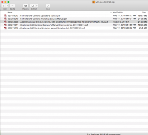
FILELIST: 883MB
327189013 – Challenger 644/645/646 Combine Operator’s Manual.pdf
327208010 – Challenger 644/645/646 Combine Workshop Service Manual.pdf
327258090 – AGCO/Challenger 645 S/645 S AL/647 S КОМБАИН РУКОВОДСТВО ПО ЭКСПЛУАТАЦИИ (RU).pdf
327272011 – Challenger 640 Combine Operator’s Manual (from serial No. 551110001).pdf
327275010 – Challenger 640 Comine Workshop Manual Updating (ref. 327208010).pdf

EXCERPT:
TABLE OF CONTENTS
Sections
– GENERAL INFORMATION …. 00
– ENGINE ……. 10
– LIVE PTO . 14
– TRANSMISSION …. 21
– FRONT DRIVE .AXLE …. 25
– HYDROSTATIC TRANSMISSION …. 29
– BRAKES AND CONTROL …. 33
– HYDRAULIC SYSTEMS …. 35
– STEERING …. 41
– AXLE AND WHEELS ……. 44
– CAB CONDITIONING SYSTEM …. 50
– ELECTRICAL SYSTEMS …. 55
– ATTACHMENTS I HEADERS ….. 58
– PRODUCT FEEDING . 60
– THRESHING …… 66
– SEPARATION …. 72
– STRAW CHOPPER …. 73
– CLEANING …. 74
– GRAIN STORAGE ….. 80

Posted on

Challenger Agricultural Tractors 65B, 65C, 65D, 65E, 70C, 75, 75C, 75D, 75E, 85C, 85D, 85E, 95E Factory Service & Shop Manual

Pressure Control Group

MCHALL65B95EOPES.zip
Price: $29.99 USD

Complete workshop & service manual with electrical wiring diagrams for Challenger Agricultural Tractors 65B, 65C, 65D, 65E, 70C, 75, 75C, 75D, 75E, 85C, 85D, 85E, 95E. It’s the same service manual used by dealers that guaranteed to be fully functional and intact without any missing page.

This service & repair manual collection for Challenger Agricultural Tractors 65B, 65C, 65D, 65E, 70C, 75, 75C, 75D, 75E, 85C, 85D, 85E, 95E (including maintenance, overhaul, disassembling & assembling, adjustment, tune-up, operation, inspecting, diagnostic & troubleshooting…) is divided into different sections. Each section covers a specific component or system with detailed illustrations. A table of contents is placed at the beginning of each section. Pages are easily found by category, and each page is expandable for great detail. The printer-ready PDF documents work like a charm on all kinds of devices.

FILELIST:
SENR5258 – Specifications (CHALLENGER 65C, 70C, 75C, & 85C AGRICULTURAL TRACTORS TRANS)
SENR5261 – Specifications (CHALLENGER 65C, 70C, 75C & 85C AGRICULTURAL TRACTORS UNDER)
SENR5263 – Disassembly & Assembly (CHALLENGER 65C, 70C, 75C & 85C AGRICULTURAL TRACTORS POWER T)
SENR5264 – Specifications (CHALLENGER 65C, 70C, 75C & 85C AGRICULTURAL TRACTORS HYDRA)
SENR5266 – Schematic (Challenger 65C, 70C, 75C, & 85C Agricultural Tractors Hydraulic System)
SENR5267 – Disassembly & Assembly (CHALLENGER 65C, 70C, 75C, & 85C AGRICULTURAL TRACTORS MACHIN)
SENR5268 – Schematic (Challenger 65C Agricultural Tractor Electrical System)
SENR5269 – Schematic (Challenger 75C Agricultural Tractor Electrical System)
SENR5273 – Systems Operation (65C, 65D, 65E, 70C, 75C, 75D, 75E, 85C, 85D, 85E & 95E Agricultural Tractors Machine Performance Panel)
SENR5316 – Schematic (Challenger 75C & 85C Agricultural Tractors Electrical System)
SENR5329 – Systems Operation (65C, 65D, 65E, 70C, 75C, 75D, 75E, 85C, 85D, 85E & 95E Agricultural Tractors Machine Monitor System)
SENR5329 – Testing & Adjusting (65C, 65D, 65E, 70C, 75C, 75D, 75E, 85C, 85D, 85E & 95E Agricultural Tractors Machine Monitor System)
SENR8334 – Schematic (Challenger 75C & 85C Agricultural Tractors Electrical System)
SENR8370 – Disassembly & Assembly (SUPPLEMENT FOR CHALLENGER 65C, 65D, 70C, 75C & 85C)
SENR8468 – Specifications (CHALLENGER 65D, 75C, & 85C AGRICULTURAL TRACTORS TRANSMISS)
SENR8471 – Specifications (CHALLENGER 65D, CHALLENGER 75C, & CHALLENGER 85C, AGRICULT)
SENR8474 – Specifications (CHALLENGER 65D, CHALLENGER 75C, & CHALLENGER 85C AGRICULTU)
SENR8476 – Schematic (Challenger 65C, Challenger 65D, Challenger 70C, Challenger 75C, & Challenger 85C Agricultural Tractors Hydraulic System)
SENR4967 – Testing & Adjusting (Challenger 65B & 75 Agricultural Tractors Undercarriage).pdf
SENR4969 – Testing & Adjusting (Challenger 65B & 75 Agricultural Tractors Hydraulic System).pdf
SENR5227 – Testing & Adjusting (Challenger 65B & 75 Agricultural Tractors Brakes).pdf
SENR5259 – Systems Operation (CHALLENGER 65C, 70C, 75C, & 85C AGRICULTURAL TRACTORS TRANS).pdf
SENR5260 – Testing & Adjusting (CHALLENGER 65C, 70C, 75C & 55C AGRICULTURAL TRACTORS TRANS).pdf
SENR5262 – Systems Operation (CHALLENGER 65C, 70C, 75C & 85C AGRICULTURAL TRACTORS UNDER).pdf
SENR5262 – Testing & Adjusting (CHALLENGER 65C, 70C, 75C & 85C AGRICULTURAL TRACTORS UNDER).pdf
SENR5265 – Systems Operation (CHALLENGER 65C, CHALLENGER 70C, CHALLENGER 75C & CHALLENGE).pdf
SENR5265 – Testing & Adjusting (CHALLENGER 65C, CHALLENGER 70C, CHALLENGER 75C & CHALLENGE).pdf
SENR5273 – Testing & Adjusting (65C, 65D, 65E, 70C, 75C, 75D, 75E, 85C, 85D, 85E & 95E Agricultural Tractors Machine Performance Panel).pdf
SENR8469 – Systems Operation (CHALLENGER 65D, 75C, & 85C AGRICULTURAL TRACTORS TRANSMISS).pdf
SENR8472 – Systems Operation (CHALLENGER 65D, CHALLENGER 75C, & CHALLENGER 85C, AGRICULT).pdf
SENR8472 – Testing & Adjusting (CHALLENGER 65D, CHALLENGER 75C, & CHALLENGER 85C, AGRICULT).pdf
SENR8475 – Systems Operation (CHALLENGER 65D, CHALLENGER 75C, & CHALLENGER 85C AGRICULTU).pdf
SENR8475 – Testing & Adjusting (CHALLENGER 65D, CHALLENGER 75C, & CHALLENGER 85C AGRICULTU).pdf
SENR8478 – Testing & Adjusting (Challenger 65C, Challenger 65D, Challenger 70C, Challenger 75C, & Challenger 85C Agricultural Tractors Hydraulic System).pdf

EXCERPT:
Pump Efficiency Check
NOTE: The steering pump must be checked on a bench that simulates the machine’s complete steering hydraulic system. The charge pump and differential lube pump can be checked on the machine or a standard bench.
For any pump test, the pump flow measured in liter/min (U.S. gpm) at 690 kPa (100 psi) is larger than the pump flow at 6900 kPa (1000 psi) at the same speed.
The difference between the pump flow of two operating pressures is the flow loss.
Method of finding flow loss:

Posted on

Challenger Agricultural Tractors 35/45/55 Factory Service & Shop Manual


Download Link

INSTANT DOWNLOAD (add to cart)

Pages from SENR5378 – Testing & Adjusting (Challenger 35, Challenger 45, & Challenger 55 Agricultural)

Complete workshop & service manual with electrical wiring diagrams for Challenger Agricultural Tractors 35/45/55. It’s the same service manual used by dealers that guaranteed to be fully functional and intact without any missing page.

This Challenger Agricultural Tractors 35/45/55 service & repair manual (including maintenance, overhaul, disassembling & assembling, adjustment, tune-up, operation, inspecting, diagnostic & troubleshooting…) is divided into different sections. Each section covers a specific component or system with detailed illustrations. A table of contents is placed at the beginning of each section. Pages are easily found by category, and each page is expandable for great detail. The printer-ready PDF documents work like a charm on all kinds of devices.

BONUS MANUAL:
79025217D – Challenger LB23B/LB24B/LB33B/LB34B/LB44B/LB23B CE/LB24B CE/LB33B CE/LB34B CE/LB44B CE Large Rectangular Baler Service Manual

FILELIST:
RENR1639 – Specifications (Challenger 35, Challenger 45 and Challenger 55 Agricultural Tractors Implement, Steering and Brake Hydraulic Systems)
RENR1640 – Systems Operation (Challenger 35, Challenger 45 and Challenger 55 Agricultural Tractors Implement, Steering and Brake Hydraulic Systems)
RENR1640 – Testing and Adjusting (Challenger 35, Challenger 45 and Challenger 55 Agricultural Tractors Implement, Steering and Brake Hydraulic Systems)
RENR1666 – Specifications (35, 45 and 55 Agricultural Tractors)
RENR1778 – Systems Operation (Challenger 35, Challenger 45 and Challenger 55 Agricultural Tractors Power Train)
RENR1778 – Testing and Adjusting (Challenger 35, Challenger 45 and Challenger 55 Agricultural Tractors Power Train)
SENR8305 – Disassembly and Assembly (Challenger 35, 45, & 55 Agricultural Tractors Transmission)
SENR8308 – Disassembly and Assembly (Challenger 35, Challenger 45 and Challenger 55 Agricultural Tractors Power Train)
SENR8311 – Schematic (Challenger 35, Challenger 45, Challenger 55 Agricultural Tractors Hydraulic System)
SENR8312 – Disassembly and Assembly (Challenger 35, Challenger 45 and Challenger 55 Agricultural Tractors Machine Systems)
SENR8313 – Schematic (Challenger 35, Challenger 45, Challenger 55 Agricultural Tractors Electrical System)
SENR5378 – Systems Operation (Challenger 35, Challenger 45, & Challenger 55 Agricultural).pdf
SENR5378 – Testing & Adjusting (Challenger 35, Challenger 45, & Challenger 55 Agricultural).pdf
SENR8310 – Systems Operation (Challenger 35, Challenger 45, & Challenger 55 Agricultural T).pdf
SENR8310 – Testing & Adjusting (Challenger 35, Challenger 45, & Challenger 55 Agricultural T).pdf

EXCERPT:
Component Description
Air Filter Vacuum Switch
The air filter vacuum switch is located in the air cleaner at the turbocharger tube. The switch is coupled to the Front Main wiring harness by two spade type connectors. The switch is normally open and closes when the vacuum in the air intake tube exceeds 635 mm (25 in) of water. When the switch is closed, the alert indicator for air filter restriction illuminates on the EMC.
Coolant Level Sensor
The engine coolant level sensor directly attaches to the radiator, near the top. A single wire connects the sensor to the CCM. The sensor acts as a normally open switch having a lower resistance when immersed in coolant. When the sensor opens (low coolant level) for at least eight seconds, the alert indicator for low coolant level illuminates on the EMC. Also the alarm horn will CONTINUOUSLY SOUND. This is a non-critical alarm.
Alternator
A signal wire connects the alternator to the CCM. If voltage is less than 11 volts, the alert indicator for the battery illuminates on the EMC. If voltage is greater than 16 volts, the alert indicator for the battery
FLASHES on the EMC. This is a non-critical alarm.
Aftercooler Temperature Sensor
The aftercooler temperature sensor is located on the right side of the engine, near the top rear. A signal wire and ground wire connect the sensor to the CCM. When the temperature is greater than 82°C (180°F) the alert indicator for aftercooler overheated illuminates on the EMC. This is a non-critical alarm.
Transmission Oil Pressure Switch

Posted on

Komatsu Hydraulic PC03, PC05, PC07, PC09, PC10, PC12, PC15, PC18, PC20, PC25, PC27, PC30, PC35, PC40, PC45, PC50, PC55 Excavator Factory Service & Shop Manual

Komatsu PC03-05-07-09-10-12-15-18-20-25-27-30-35-40-45-50-55 Hydraulic Excavator

MKMTSPC0355OPEK.PDF
Price: $29.99 USD

Complete workshop & service manual with electrical wiring diagrams for Komatsu Hydraulic Excavator PC03-2, PC05-6, PC07-1, PC09-1, PC10-6, PC10-7, PC12R-8, PC15MR-1, PC15-2, PC15-3, PC15R-8, PC18MR-2, PC18MR-3, PC20-3, PC20MRX-1, PC20MR-2, PC20-6, PC20-7, PC20R-8, PC25-1, PC25R-8, PC27MRX-1, PC27MR-2, PC27MR-3, PC27R-8, PC30MRX-1, PC30MR-2, PC30-3, PC30MR-3, PC30-6, PC30-7, PC30R-8, PC35MRX-1, PC35MR-2, PC35MR-3, PC35R-8, PC40MRX-1, PC40MR-2, PC40-6, PC40-7, PC40R-8, PC45-1, PC45MRX-1, PC45MR-3, PC45R-8, PC50UU-1, PC50MR-2, PC50UU-2, PC55MR-3. It’s the same service manual used by dealers that guaranteed to be fully functional and intact without any missing page.

This Komatsu Hydraulic Excavator PC03-2, PC05-6, PC07-1, PC09-1, PC10-6, PC10-7, PC12R-8, PC15MR-1, PC15-2, PC15-3, PC15R-8, PC18MR-2, PC18MR-3, PC20-3, PC20MRX-1, PC20MR-2, PC20-6, PC20-7, PC20R-8, PC25-1, PC25R-8, PC27MRX-1, PC27MR-2, PC27MR-3, PC27R-8, PC30MRX-1, PC30MR-2, PC30-3, PC30MR-3, PC30-6, PC30-7, PC30R-8, PC35MRX-1, PC35MR-2, PC35MR-3, PC35R-8, PC40MRX-1, PC40MR-2, PC40-6, PC40-7, PC40R-8, PC45-1, PC45MRX-1, PC45MR-3, PC45R-8, PC50UU-1, PC50MR-2, PC50UU-2, PC55MR-3 service & repair manual (including maintenance, overhaul, disassembling & assembling, adjustment, tune-up, operation, inspecting, diagnostic & troubleshooting…) is divided into different sections. Each section covers a specific component or system with detailed illustrations. A table of contents is placed at the beginning of each section. Pages are easily found by category, and each page is expandable for great detail. The printer-ready PDF documents work like a charm on all kinds of devices.

FILELIST (1.57 GB PDF):
EEPB000800 – Hydraulic Excavator PC05-6F Parts Book.pdf
SEAM020MB600 – Hydraulic Excavator PC05-6, PC10-6, PC15-2 Operation & Maintenance Manual.pdf
SEAM020P0700 – Hydraulic Excavator PC20-7 Operation & Maintenance Manual.pdf
SEAM020U0100 – Hydraulic Excavator PC50UU-1 Operation & Maintenance Manual.pdf
SEAM020U0101 – Hydraulic Excavator PC50UU-1 Operation & Maintenance Manual.pdf
SEAM005500 – Hydraulic Excavator PC50UU-2 Operation & Maintenance Manual.pdf
SEAM005503T – Hydraulic Excavator PC50UU-2 Operation & Maintenance Manual.pdf
SEAM006600 – Hydraulic Excavator PC25-1, PC30-7, PC40-7, PC45-1 Operation & Maintenance Manual.pdf
SEAM009502T – Hydraulic Excavator PC40-7 Operation & Maintenance Manual.pdf
SEAM015102T – Hydraulic Excavator PC12R-8, PC15R-8 Operation & Maintenance Manual.pdf
SEAM015203T – Hydraulic Excavator PC20R-8, PC25R-8, PC27R-8 Operation & Maintenance Manual.pdf
SEAM015301 – Hydraulic Excavator PC30R-8, PC35R-8, PC40R-8, PC45R-8 Operation & Maintenance Manual.pdf
SEAM015304T – Hydraulic Excavator PC35R-8, PC45R-8 Operation & Maintenance Manual.pdf
SEAM034800 – Hydraulic Excavator PC28UU-2 Operation & Maintenance Manual.pdf
SEAM035202T – Hydraulic Excavator PC20MRx-1Operation & Maintenance Manual.pdf
SEAM035203 – Hydraulic Excavator PC20MRx-1 Operation & Maintenance Manual.pdf
SEAM035305T – Hydraulic Excavator PC27MR-x1, PC30MR-x1, PC35MR-x1 Operation & Maintenance Manual.pdf
SEAM040601 – Hydraulic Excavator PC03-2 Operation & Maintenance Manual.pdf
SEAM043000 – Hydraulic Excavator PC40MRx-1, PC45MRx-1 Operation & Maintenance Manual.pdf
SEAM043006T – Hydraulic Excavator PC40MRx-1, PC45MRx-1 Operation & Maintenance Manual.pdf
SEAM044501T – Hydraulic Excavator GALEO PC09-1 Operation & Maintenance Manual.pdf
SEAM044502 – Hydraulic Excavator PC09-1 Operation & Maintenance Manual.pdf
SEAM044900T – Hydraulic Excavator PC15MRX-1 Operation & Maintenance Manual.pdf
SEAM055301T – Hydraulic Excavator GALEO PC40MR-2, PC50MR-2 Operation & Maintenance Manual.pdf
SEAM060100T – Hydraulic Excavator GALEO PC35MR-2 Operation & Maintenance Manual.pdf
SEBM020M0604 – Hydraulic Excavator PC05-6, PC07-1, PC10-6, PC15-2 Shop Manual.pdf
SEBM020P0703 – Hydraulic Excavator PC10-7, PC15-3, PC20-7 Shop Manual.pdf
SEBM020R0604 – Hydraulic Excavator PC20-6, PC30-6, PC40-6 Shop Manual.pdf
SEBM020S0707 – Hydraulic Excavator PC25-1, PC30-7, PC40-7, PC45-1 Shop Manual.pdf
SEBM020U0104 – Hydraulic Excavator PC50UU-1 Shop Manual.pdf
SEBM0225C01 – Hydraulic Excavator PC20-3, PC30-3 Shop Manual.pdf
SEBM000906 – Hydraulic Excavator PC50UU-2 Shop Manual.pdf
SEBM010801 – Hydraulic Excavator PC20R-8, PC25R-8, PC27R-8 Shop Manual.pdf
SEBM012603 – Hydraulic Excavator PC30R-8, PC35R-8, PC40R-8, PC45R-8 Shop Manual.pdf
SEBM012604 – Hydraulic Excavator PC30R-8, PC35R-8, PC40R-8, PC45R-8 Shop Manual.pdf
SEBM013103 – Hydraulic Excavator PC12R-8, PC15R-8 Shop Manual.pdf
SEBM016602 – Hydraulic Excavator PC20MRX-1 Shop Manual.pdf
SEBM016808 – Hydraulic PC27MRX-1, PC30MRX-1, PC35MRX-1, PC40MRX-1, PC45MRX-1 Shop Manual.pdf
SEBM019002 – Hydraulic Excavator PC15MR-1 Shop Manual.pdf
SEBM025000 – Hydraulic Excavator PC03-2 Shop Manual.pdf
SEBM026105 – Hydraulic Excavator PC09-1 Shop Manual.pdf
SEBM032411 – Hydraulic Excavator PC27MR-2, PC30MR-2, PC35MR-2, PC40MR-2, PC50MR-2 Shop Manual.pdf
SEBM037001 – Hydraulic Excavator PC20MR-2 Shop Manual.pdf
SEBM038404 – Hydraulic Excavator PC18MR-2 Shop Manual.pdf
SEN04063-07 – Hydraulic Excavator PC27MR-3, PC30MR-3, PC35MR-3 Shop Manual.pdf
SEN04306-04 – Hydraulic Excavator PC18MR-3 Shop Manual.pdf
SEN04597-06 – Hydraulic Excavator PC45MR-3, PC55MR-3 Shop Manual.pdf
TEN00052-01 – Hydraulic Excavator GALEO PC18MR-2 Operation & Maintenance Manual.pdf
TEN00054-03 – Hydraulic Excavator GALEO PC40MR-2, PC50MR-2 Operation & Maintenance Manual.pdf
TEN00062-04 – Hydraulic Excavator PC09-1 Operation & Maintenance Manual.pdf
TEN00099-01 – Hydraulic Excavator PC27MR-2, PC35MR-2 Operation & Maintenance Manual.pdf
TEN00101-02 – Hydraulic Excavator GALEO PC20MR-2 Operation & Maintenance Manual.pdf
TEN00115-00 – Hydraulic Excavator GALEO PC27ME-2, PC35MR-2 Operation & Maintenance Manual.pdf
TEN00115-01 – Hydraulic Excavator GALEO PC27MR-2, PC35MR-2 Operation & Maintenance Manual.pdf
TEN00193-00 – Hydraulic Excavator GALEO PC40MR-2, PC50MR-2 Operation & Maintenance Manual.pdf
TEN00194-00 – Hydraulic Excavator GALEO PC27MR-2, PC35MR-2 Operation & Maintenance Manual.pdf
TEN00284-03 – Hydraulic Excavator GALEO PC27MR-3, PC35MR-3 Operation & Maintenance Manual.pdf
TEN00292-03 – Hydraulic Excavator PC18MR-3 Operation & Maintenance Manual.pdf
TEN00306-03 – Hydraulic Excavator PC45MR-3, PC55MR-3 Operation & Maintenance Manual.pdf
TEN00378-03 – Hydraulic Excavator PC27MR-3, PC35MR-3 Operation & Maintenance Manual.pdf
TEN00390-03 – Hydraulic Excavator PC45MR-3, PC55MR-3 Operation & Maintenance Manual.pdf
TEN00507-01 – Hydraulic Excavator PC27MR-3, PC35MR-3 Operation & Maintenance Manual.pdf
TEN00508-01 – Hydraulic Excavator PC45MR-3, PC55MR-3 Operation & Maintenance Manual.pdf
TEN00514-01 – Hydraulic Excavator PC18MR-3 Operation & Maintenance Manual.pdf
TEN00549-00 – Hydraulic Excavator PC18MR-3 Operation & Maintenance Manual.pdf
TEN00552-01 – Hydraulic Excavator PC27MR-3, PC35MR-3 Operation & Maintenance Manual.pdf
TEN00555-00 – Hydraulic Excavator PC09-1 Operation & Maintenance Manual.pdf
WEAM000101 – Hydraulic Excavator PC20R-8, PC27R-8 Operation & Maintenance Manual.pdf
WEAM002702 – Hydraulic Excavator PC12R-8, PC12R-8 HS, PC15R-8, PC15R-8 HS Operation & Maintenance Manual.pdf
WEAM003000 – Hydraulic Excavator PC15R-8 Operation & Maintenance Manual.pdf
WEAM003001 – Hydraulic Excavator PC15R-8 Deluxe Operation & Maintenance Manual.pdf
WEAM003100 – Hydraulic Excavator PC27R-8 Operation & Maintenance Manual.pdf
WEAM003102 – Hydraulic Excavator PC27R-8 Deluxe Operation & Maintenance Manual.pdf
WEAM003200 – Hydraulic Excavator PC35R-8, PC45R-8 Operation & Maintenance Manual.pdf
WEAM003202 – Hydraulic Excavator PC35R-8, PC45R-8 Deluxe Operation & Maintenance Manual.pdf
WEAM006600 – Hydraulic Excavator PC30MR-2, PC35MR-2 Operation & Maintenance Manual.pdf
WEAM007000 – Hydraulic Excavator GALEO PC20MR-2 Operation & Maintenance Manual.pdf
WEAM007700 – Hydraulic Excavator GALEO PC14R-2 Operation & Maintenance Manual.pdf
WEAM007800 – Hydraulic Excavator GALEO PC16R-2 Operation & Maintenance Manual.pdf
WEBM000100 – Hydraulic Excavator PC12R-8, PC15R-8 Shop Manual.pdf
WEBM000101 – Hydraulic Excavator PC12R-8, PC15R-8 Shop Manual.pdf
WEBM000200 – Hydraulic Excavator PC20R-8, PC27R-8 Shop Manual.pdf
WEBM000201 – Hydraulic Excavator PC20R-8, PC27R-8 Shop Manual.pdf
WEBM002800 – Hydraulic Excavator PC15R-8 Shop Manual.pdf
WEBM002900 – Hydraulic Excavator PC27R-8 Shop Manual.pdf
WEBM003000 – Hydraulic Excavator PC35R-8, PC45R-8 Shop Manual.pdf
WEBM003800 – Hydraulic Excavator PC27R-8 Deluxe Shop Manual.pdf
WEBM003900 – Hydraulic Excavator PC35R-8, PC45R-8 Deluxe Shop Manual.pdf

EXCERPT:
ADJUSTMENT OF VALVE CLEARANCE
• Adjust the clearance between valve and rockers to the following values:
With engine cold – Suction valves 0.20 – Exhaust valve 0.20
1 – Remove the valve cover.
2 – Rotate the drive shaft in the normal direction of rotation, until the No. 1 cylinder is in the top dead centre in a compression stroke corresponding to the alignment between the reference mark on the casing (1) and the mark (2) on the pulley.
* If the cylinder is in a compression stroke, the valves do not move when the drive shaft is rotated slightly. If the valves do move, rotate the drive shaft by one turn and realign the reference marks (1) and (2).
3 – Loosen the lock nut (3) and unscrew the adjustment screw (6) by approximately 1 turn.
* Check that the valve cap (5) is lying flat on the valve stem and that there is no lopsided wear.
1 – If the valve caps (5) are damaged, replace them with new ones.
2 – Make sure that the valve caps fit perfectly and are lying flat on the valve stem.”
4 – Insert the feeler gauge A1 between the rocker (4) and the valve cap (5).
Rotate the adjusting screw (6) until it rubs against the feeler gauge A1.
Secure this position with the nut (3).
Lock nut: 25.5±2.5 Nm
* After locking the nut (3), check the valve clearance again.
5 – After adjusting the No. 1 cylinder, rotate the drive shaft 240° each time and adjust the valve clearance of the other cylinders according to the ignition sequence.
* Ignition sequence: 1 – 3 – 2.
• Assembly of the valve cover
1 – Check the condition of the gasket (7) of the valve cover (8), and the 0-rings (9). Thoroughly clean the contact surface on the cylinder heads.
2 – Replace the valve cover (8) and mount the 0-rings
(9) and the lock nuts (10).
Lock nuts for cover: 25±3 Nm
…
STRUCTURE, FUNCTION AND MAINTENANCE STANDARD – OPERATION FOR EACH FUNCTION AND VALVE
L.H., R.H. TRAVEL JUNCTION CIRCUIT PC27MR, 30MR-2
1. When traveling in a straight line
FUNCTION
ï To compensate for any difference in the oil flow in the left and right travel circuits when traveling in a straight line, the junction circuit opens when the left and right travel spools are operated.
ï In this way, the flow of oil to the left and right travel motors is almost the same when traveling in a straight line, so there is no travel deviation.
ï When steering the machine, the difference in the load pressure returns the reducing valve of the travel valve on the inside of the turn and the opening of the notch in the travel junction valve spool becomes smaller, so the machine can be steered.
OPERATION
ï When left and right travel spools (1) are operated, the pump discharge flows from pump circuit PP and circuits PA to actuator circuits B.
ï When traveling in a straight line, to make actuator circuits PA equal, left and right reducing valves (2) are pushed to the right by the same amount, and notch a and the travel junction circuit are opened.
ï In this way, the left and right travel actuator circuits are interconnected by the travel junction circuit, so if any difference occurs in the flow of oil to the left and right travel motors, the compensation is carried out to prevent any deviation in travel.
2. Steering when traveling
OPERATION
• When traveling in a straight line, if left travel spool (L. H. 1) is returned to the neutral position and the steering is operated, a difference (R. H. B > L. H. B) is generated in the load pressure of left and right travel actuator circuits PA, and LS pressure PLS becomes the same pressure as R.
H. B.
• As a result, flow control valve (3) on the left travel side is pushed to the left by LS circuit PLS.
Because of this, the opening of the left notch a is made smaller, so it becomes possible to operate the steering when traveling.
• Damper b is provided in the circuit to damper any excessive characteristics in the opening or closing of the travel junction circuit if the spool is operated suddenly.

Posted on

Komatsu HB205, HB215LC Hybrid Workshop Repair & Service Manual

Komatsu HB205, HB215LC Hybrid


INSTANT DOWNLOAD


Complete digital official shop manual contains service, maintenance, and troubleshooting information for the Komatsu HB205-1, HB215LC-1 Hybrid Hydraulic Excavator. Diagnostic and repair procedures are covered in great detail to repair, maintain, rebuild, refurbish or restore your HB205, HB215LC like a professional mechanic in local service/repair workshop. This cost-effective quality manual is 100% complete and intact as should be without any missing pages. It is the same factory shop manual used by dealers that guaranteed to be fully functional to save your precious time.

This manual for Komatsu HB205-1, HB215LC-1 Hybrid Hydraulic Excavator is divided into different sections. Each section covers a specific component or system and, in addition to the standard service procedures, includes disassembling, inspecting, and assembling instructions. A table of contents is placed at the beginning of each section. Pages are easily found by category, and each page is expandable for great detail. It is in the cross-platform PDF document format so that it works like a charm on all kinds of devices. You do not need to be skilled with a computer to use the manual.

“Shop Manual (SEN05393-04).pdf”
Komatsu HB205-1, HB215LC-1 Hybrid Hydraulic Excavator Shop Manual; 1,451 pages

EXCERPT:

General information on troubleshooting – Checks before troubleshooting

Replacing fuel pre-filter cartridge
1. Turn valve (1) at the bottom of the fuel tank to the “CLOSE” (S) position.
2. Open the side cover on the rear right side of the machine.
3. Place a container under the fuel pre-filter cartridge to receive the fuel.
4. Loosen drain valve (2) and drain water and sediments from transparent cup (3), and also drain all the fuel from filter cartridge (4).
5. Disconnect connector (5). Wrap the removed connector with a vinyl bag or the like to protect it from being exposed to fuel, oil and water.
6. Using the filter wrench, rotate transparent cap (3) to remove. (This cap is reused.)
7. Using the filter wrench, rotate filter cartridge (4) to remove.
8. Install currently removed transparent cap (3) to the bottom of the new filter cartridge.
– At this time, replace O-ring (6) with a new one.
9. When installing the transparent cap, apply a thin film of oil to the O-ring, set it against the sealing surface of filter cartridge (4), and then tighten the transparent cap 1/4 to 1/2 turn.
– If the transparent cap is over tightened, fuel will leak because the O-ring will have been damaged. If the transparent cap is not tightened sufficiently, fuel will also leak through the clearance around the O-ring. Therefore, observe the tightening angle.
10. Clean the filter holder, fill the new filter cartridge with clean fuel, apply a thin film of oil to the O-ring, and then install the new filter cartridge with the O-ring on the filter holder.
– Be sure to add fuel through eight small holes (A) which are on the dirty side of the filter without removing center cap (B).
– After filling with the fuel, remove center cap (B) before installing the fuel pre-filter.
– Add clean fuel taking care not to allow dirt to mix in it. Be sure to add fuel without removing center cap (B) which is on the clean side of the filter to prevent dirt from entering.


INSTANT DOWNLOAD