Posted on

Bobcat 319 Compact Excavator Factory Service & Shop Manual

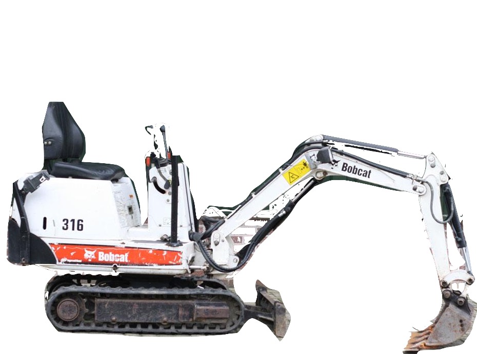
Pages from Service Manual (319 Compact Excavator) 6904188 (2-06)

MBOBC319OPEK.PDF
Price: $29.99 USD

Complete workshop & service manual with electrical wiring diagrams for Bobcat 319 Compact Excavator. It’s the same service manual used by dealers that guaranteed to be fully functional and intact without any missing page.

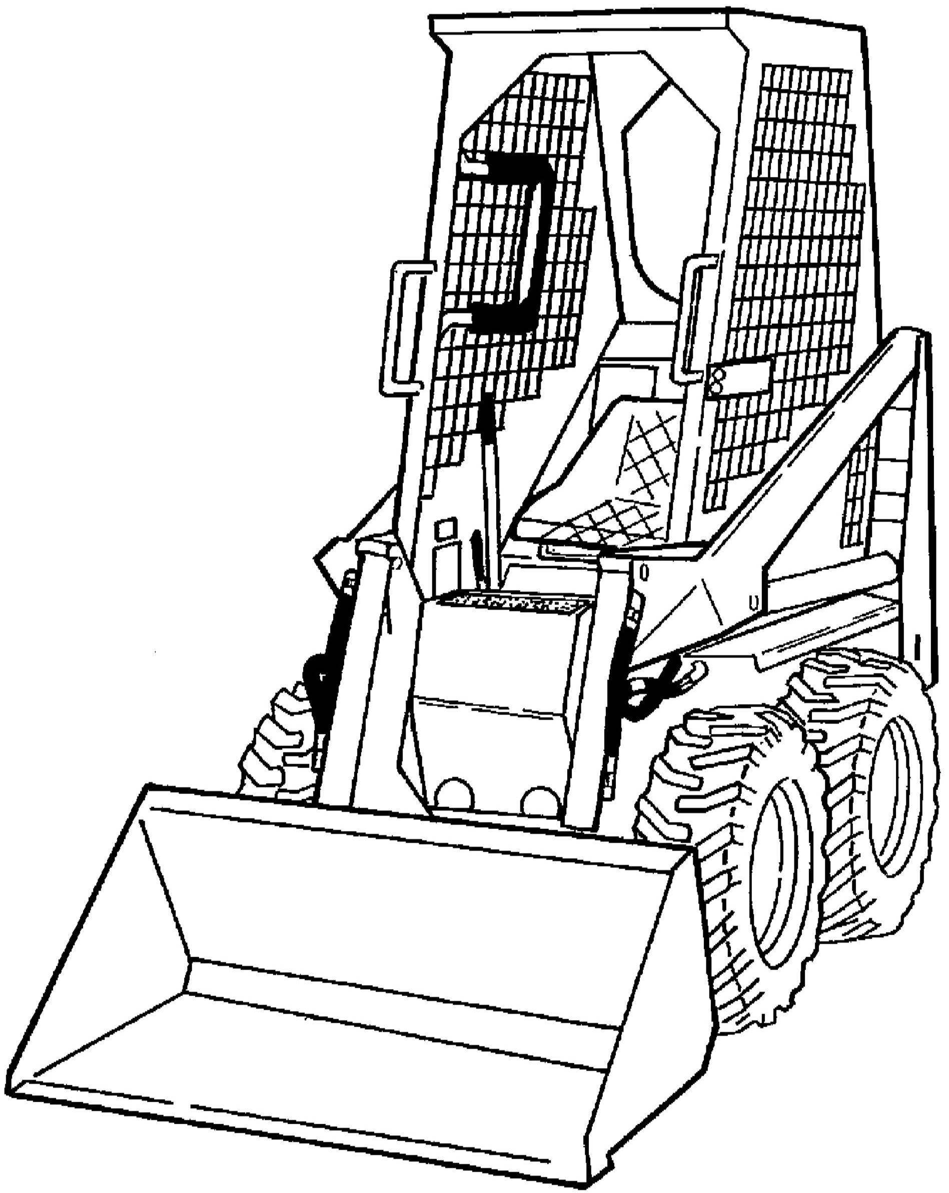
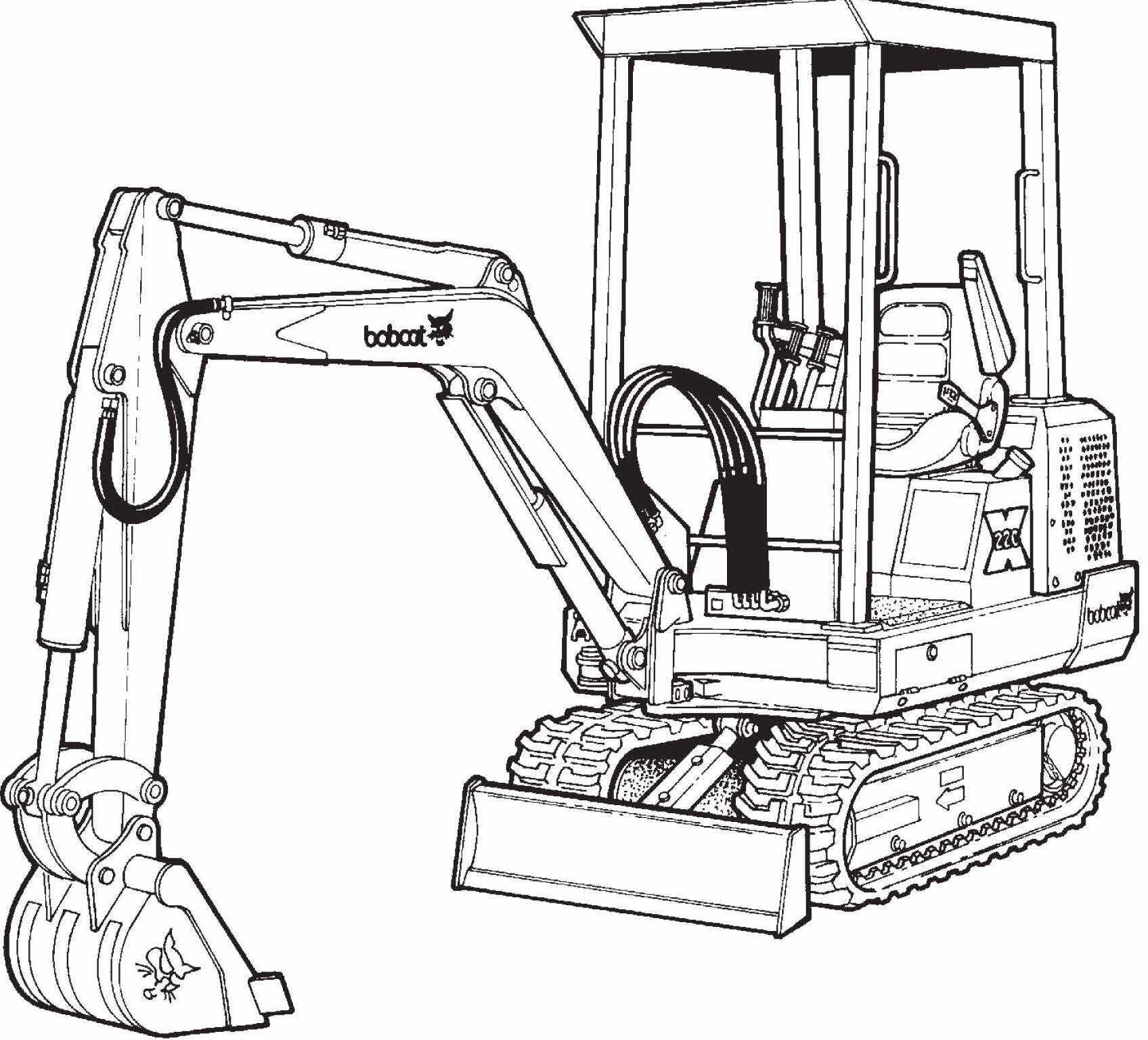
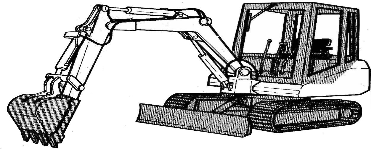
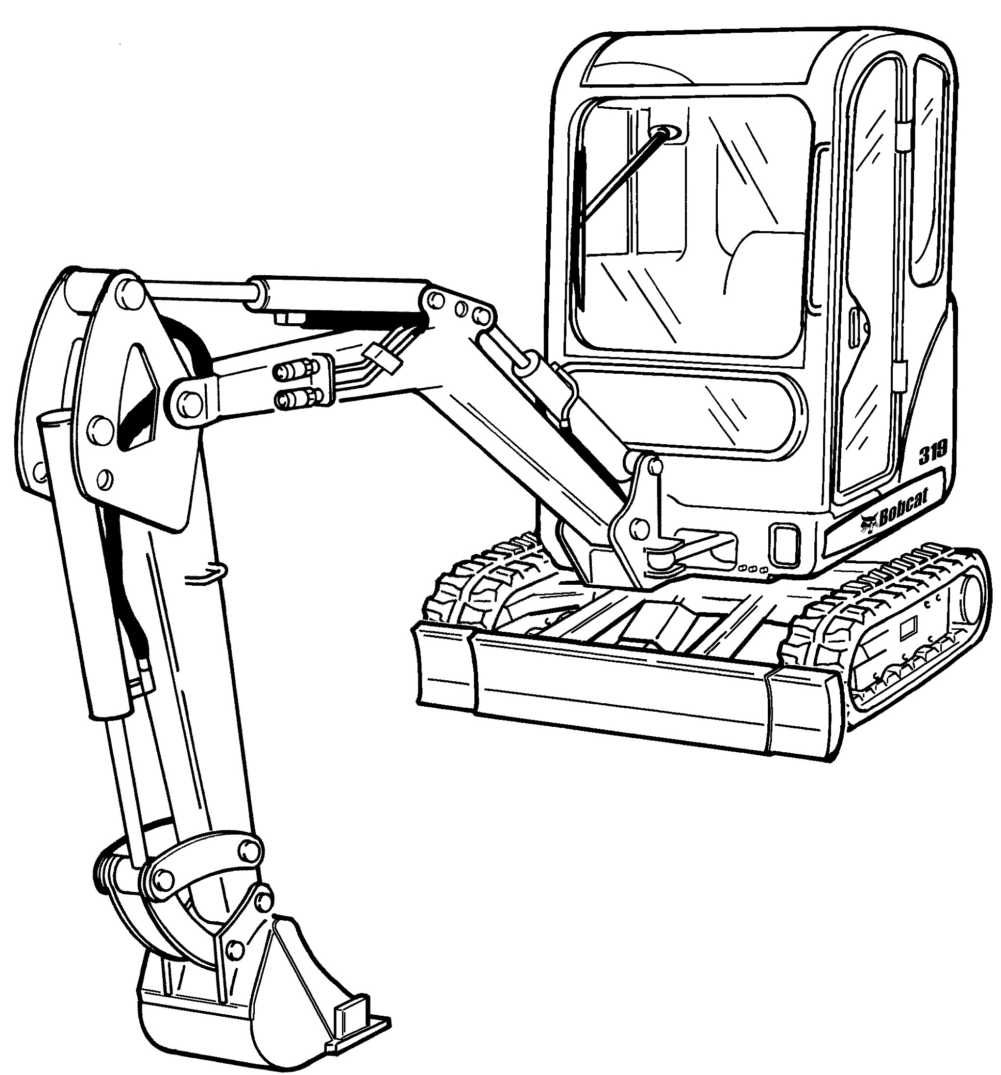
This Bobcat 319 Compact Excavator service & repair manual (including maintenance, overhaul, disassembling & assembling, adjustment, tune-up, operation, inspecting, diagnostic & troubleshooting…) is divided into different sections. Each section covers a specific component or system with detailed illustrations. A table of contents is placed at the beginning of each section. Pages are easily found by category, and each page is expandable for great detail. The printer-ready PDF documents work like a charm on all kinds of devices.

Operation & Maintenance Manual (319 Compact Excavator) 6904116 (10-05).pdf
Service Manual (319 Compact Excavator) 6904188 (2-06).pdf
Schematics

EXCERPT:
CONTENTS
FOREWORD. . . . . . . . . . . . . . . . . . . . . . . . . . . . . . . . . . . . . . III
SAFETY INSTRUCTIONS . . . . . . . . . . . . . . . . . . . . . . . . . . . . . . . . V
SERIAL NUMBER LOCATIONS . . . . . . . . . . . . . . . . . . . . . . . . . . . . IX
DELIVERY REPORT. . . . . . . . . . . . . . . . . . . . . . . . . . . . . . . . . . . . . X
EXCAVATOR IDENTIFICATION . . . . . . . . . . . . . . . . . . . . . . . . . . . .XI
SAFETY AND MAINTENANCE. . . . . . . . . . . . . . . . . . . . . . . . . . 10-01
HYDRAULIC SYSTEM . . . . . . . . . . . . . . . . . . . . . . . . . . . . . . . . 20-01
UNDERCARRIAGE. . . . . . . . . . . . . . . . . . . . . . . . . . . . . . . . . . . 30-01
UPPERSTRUCTURE & SWING SECTION . . . . . . . . . . . . . . . . 40-01
ELECTRICAL SYSTEM AND ANALYSIS . . . . . . . . . . . . . . . . . . 50-01
ENGINE SERVICE . . . . . . . . . . . . . . . . . . . . . . . . . . .. . . . . . . . 60-01
HEATER . . . . . . . . . . . . . . . . . . . . . . . . . . . . . . . . . . . . . 70-01
SPECIFICATIONS. . . . . . . . . . . . . . . . . . . . . . . . . . . . . . . . . SPEC-01

SAFETY AND MAINTENANCE
HYDRAULIC SYSTEM
UNDERCARRIAGE
UPPERSTRUCTURE & SWING SECTION
ELECTRICAL SYSTEM AND ANALYSISRI
ENGINE SERVICE
HEATER
SPECIFICATIONS

RIGHT CONTROL LEVER (JOYSTICK) (CONT’D)
Disassembly
Remove the right handle. (See Handle Removal And Installation on Page 20-100-3.)
Clean the outside of the control lever before disassembly.
Figure 20-100-11

Posted on

Bobcat 316 Excavator Factory Service & Shop Manual

Service Manual (316 Excavator) 6902285 (2-06)

MBOBC316OPEK.PDF
Price: $29.99 USD

Complete workshop & service manual with electrical wiring diagrams for Bobcat 316 Excavator. It’s the same service manual used by dealers that guaranteed to be fully functional and intact without any missing page.

This Bobcat 316 Excavator service & repair manual (including maintenance, overhaul, disassembling & assembling, adjustment, tune-up, operation, inspecting, diagnostic & troubleshooting…) is divided into different sections. Each section covers a specific component or system with detailed illustrations. A table of contents is placed at the beginning of each section. Pages are easily found by category, and each page is expandable for great detail. The printer-ready PDF documents work like a charm on all kinds of devices.

Operation & Maintenance Manual (316 Excavator) 6902283 (12-05).pdf
Service Manual (316 Excavator) 6902285 (2-06).pdf

EXCERPT:
Replacement:
When the cracks reach so deep that they expose the steel cords, track replacement is required.
Causes Of The Damage:
Because of wound stress applied to rubber tracks around the undercarriage parts during operation, the fatigue especially causes cracks on the lug side rubber surface.
Once the cracks occur, they gradually deteriorate with even small external cracks. Also when operating near seashores or under cold temperatures, rubber tracks are more likely to suffer from ozone cracks.
Prevention:
Rubber tracks are designed with special rubber compounds to prevent cracks due to fatigue. However, external injuries on the lug side rubber sometimes cause more chance of cracking. Machine operators should observe soil conditions when driving, so as not to cause external injuries to the lug side rubber. In order to minimize the occurrence of ozone cracks, attention should be paid to the following instructions for maintenance:
Avoid exposing stored tracks to direct sun light.
Avoid exposing stored tracks to direct rain and snow fall.
Store tracks in well ventilated warehouses.
Use the tracks at least once a month.

Posted on

Bobcat 310, 313 Loader Factory Service & Shop Manual

Pages from Service Manual (310, 313 Loader) 6556606 (12-82)

MBOBC310313OPEK.PDF
Price: $29.99 USD

Complete workshop & service manual with electrical wiring diagrams for Bobcat 310, 313 Loader. It’s the same service manual used by dealers that guaranteed to be fully functional and intact without any missing page.

This Bobcat 310, 313 Loader service & repair manual (including maintenance, overhaul, disassembling & assembling, adjustment, tune-up, operation, inspecting, diagnostic & troubleshooting…) is divided into different sections. Each section covers a specific component or system with detailed illustrations. A table of contents is placed at the beginning of each section. Pages are easily found by category, and each page is expandable for great detail. The printer-ready PDF documents work like a charm on all kinds of devices.

Operation & Maintenance Manual (310 Loader) 6556215 (9-81).pdf
Operation & Maintenance Manual (313 Loader) 6556353 (4-83).pdf
Service Manual (310, 313 Loader) 6556606 (12-82).pdf

EXCERPT:
“7-1.4 Timing the FuelSystem”
“Timing of the fuel injection system is done by changing the number of shims between the injection pump and the gear-case housing (Fig. 7-3). Each shim will change the timing 1.5 degrees. The timing of the fuel injection pump will be later when a shim is added and earlier when a shim is removed. Adjust the timing so the “”1FL”” mark on the flywheel cover will align with the mark on the flywheel (Fig. 7-5). Fuel delivery must begin when these marks are in alignment.”
“To time the fuel system:”
“(1) Install a short pipe to the outlet connection for the number one injector nozzle. Point the pipe up (Vertical).”
“(2) With fuel supply to the injection pump turned on, rotate the flywheel in a counterclockwise direction. Fuel must flow from the pipe as soon as the mark on the flywheel comes in alignment with the “”1FL”” mark on the flywheel cover (Fig. 7-5).”
“(3) Add or subtract shims as necessary to adjust the delivery time of the fuel. Each shim will change the timing by 1.5 degrees. Add shims to delay fuel delivery. Subtract shims to advance time of fuel delivery.”
“7-1.5 Fuel Lift Pump I Fig. 7-6)”
“Fig. 7-5 Flywheel Timing Marks”
“The electrical fuel lift pump is engerised by the key switch circuit . It operates on 12 volt DC and is grounded by the bolts which fasten it to the engine.”
“Fuel pressure is 3 to 4.5 PSI at zero volume delivery (no flow).”
“Be sure to disconnect the battery ground cable when removing the fuel lift pump, to avoid possible spark ignition of fuel.”

Posted on

Bobcat 220, X220 Excavator Factory Service & Shop Manual

Pages from Service Manual (X220 Excavator) 6720503 (6-90)

MBOBC220OPEK.PDF
Price: $29.99 USD

Complete workshop & service manual with electrical wiring diagrams for Bobcat 220, X220 Excavator. It’s the same service manual used by dealers that guaranteed to be fully functional and intact without any missing page.

This Bobcat 220, X220 Excavator service & repair manual (including maintenance, overhaul, disassembling & assembling, adjustment, tune-up, operation, inspecting, diagnostic & troubleshooting…) is divided into different sections. Each section covers a specific component or system with detailed illustrations. A table of contents is placed at the beginning of each section. Pages are easily found by category, and each page is expandable for great detail. The printer-ready PDF documents work like a charm on all kinds of devices.

FILELIST:
Operation & Maintenance Manual (220 Excavator) 6720124 (11-89).pdf
Operation & Maintenance Manual (220 Excavator) 6720379 (11-89).pdf
Operation & Maintenance Manual (220 Excavator) 6720448 (4-92).pdf
Operation & Maintenance Manual (X220 Excavator) 6722250 (10-98).pdf
Service Manual (220 Excavator) 6722345 (9-92).pdf
Service Manual (X220 Excavator) 6720230 (5-89).pdf
Service Manual (X220 Excavator) 6720503 (6-90).pdf

EXCERPT:
“SWING MOTOR (Cont’d)”
“Assembly (Cont’d)”
“Clamp the shaft and bearing housing so the output shaft is down.”
“Pour a small amount of clean hydraulic fluid into the shaft and bearing housing for start–up lubrication.”
“Install the shaft face seal and wear plate as shown [A]. Install the drive, Geroler and valve drive.”
“Motor Timing”
“The direction that the output shaft rotates is determined by timing. Time the motor as follows:”
“Locate the largest open pocket in the Geroler (Item 1) [B]. Install the valve plate (Item 2) [B] and locate the open slot that is over the largest open Geroler pocket.”
“Align one of the side openings in the valve with the valve plate slot that is over the largest open Geroler pocket.”
“Engage the valve with the valve drive (Item 3) [B] by rotating it clockwise until the spline teeth mesh (1/2 tooth).”
“Install the inner and outer face seals on the balance ring as shown [C].”
“Install the springs, pins and balance ring in the valve housing. Hold the balance ring in place, through the forward port in the valve housing, while installing the valve housing over the valve.”
“Install and tighten the four bolts in a crisscross pattern. Tighten the bolts to 450 in.–lbs. (50 Nm) torque. Tighten the case drain plug to 50 in.–lbs. (5,5 Nm) torque.”

Posted on

Bobcat 130 Hydraulic Excavator Factory Service & Shop Manual

Service Manual (130 Hydraulic Excavator) 6570485 (4-87)

MBOBC130OPEK.PDF
Price: $29.99 USD

Complete workshop & service manual with electrical wiring diagrams for Bobcat 130 Hydraulic Excavator. It’s the same service manual used by dealers that guaranteed to be fully functional and intact without any missing page.

This Bobcat 130 Hydraulic Excavator service & repair manual (including maintenance, overhaul, disassembling & assembling, adjustment, tune-up, operation, inspecting, diagnostic & troubleshooting…) is divided into different sections. Each section covers a specific component or system with detailed illustrations. A table of contents is placed at the beginning of each section. Pages are easily found by category, and each page is expandable for great detail. The printer-ready PDF documents work like a charm on all kinds of devices.

EXCERPT:
CONTENTS
10 ENGINE
11 STRUCTURE AND FUNCTION
12 TESTING AND ADJUSTING
13 DISASSEMBLY AND ASSEMBLY1
20 POWER TRAIN
21 STRUCTURE AND FUNCTION
23 DISASSEMBLY AND ASSEMBLY
24 MAINTENANCE STANDARD
30 UNDERCARRIAGE
31 STRUCTURE AND FUNCTION
33 DISASSEMBLY AND ASSEMBLY
34 MAINTENANCE STANDARD
60 HYDRAULIC SYSTEM
61 STRUCTURE AND FUNCTION
62 TESTING AND ADJUSTING
63 DISASSEMBLY AND ASSEMBLY
64 MAINTENANCE STANDARD
70 WORK EQUIPMENT
7 3 DISASS.EMBL Y AND ASSEMBLY
80 ELECTRICAL SYSTEM
81 STRUCTURE AND FUNCTION
NOTE: This machine has a 24 volt electrical system.

SWING PRIORITY VALVE
OPERATION
Swing at neutral
• When the swing is at neutral, no pilot pressure oil flows from the solenoid valve. The swing priority valve is not actuated, so the pressurized oil from the front main pump passes through port P1 and flows to the arm-Lo control valve.
When operating swing
When the swing is operated, the limit switch on the linkage is actuated. This actuates the solenoid valve, and pilot pressure acts on port PB4 of the swing priority valve, and pushes the spool to the left.
When this happens, the pressurized oil flowing from the front main pump to the arm low control valve is restricted by the swing priority valve. The arm speed is controlled,· so simultaneous operations are made easier.