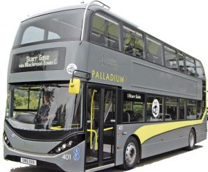
Complete workshop & service manual with electrical wiring diagrams for Alexander Dennis Enviro 400 Busses. It’s the same service manual used by dealers that guaranteed to be fully functional and intact without any missing page.
This Alexander Dennis Enviro 400 Busses (EURO3/EURO4/EURO4+) service & repair manual (including maintenance, overhaul, disassembling & assembling, adjustment, tune-up, operation, inspecting, diagnostic & troubleshooting…) is divided into different sections. Each section covers a specific component or system with detailed illustrations. A table of contents is placed at the beginning of each section. Pages are easily found by category, and each page is expandable for great detail. The printer-ready PDF documents work like a charm on all kinds of devices.
MAKE: Alexander Dennis
MODEL: Enviro 400 (EURO3/EURO4&4+)
FORMAT: PDF
2291.pdf:
Enviro 400 (EURO 4&4+) 4 & 6 cylinder Service Manual
Date: July 2006 (03/08); 474 pages
2292.pdf:
Enviro 400 (EURO 3) Service Manual
Date: December 2005 (03/06); 450 pages
2297.pdf:
Enviro 400 (EURO 4&4+) Service Manual
Date: March 2006 (10/07); 466 pages
EXCERPT:
Air Suspension System Amended
“Description”
“The vehicle is fitted with air suspension, a function of this is the facility to kneel the vehicle at the front, or when fitted, an option to lower the suspension all round.”
“The air suspension is supplied from an auxiliary tank, sited on the right hand side of the chassis and forward of the battery carrier. Output supply passes through the system line filter, which filters the air before it enters the solenoid valve block and the levelling valves. Foreign matter in these items may cause them to malfunction.”
“Levelling valves are fitted to the front and rear axles of the vehicle. The levelling valves have a neutral or zero setting and at this position the vehicle ride height is set. Should the vehicle experience an increase in load, the chassis will move nearer to the ground resulting in the connection linkage pushing up and the valve spindle turning clockwise. This results in the valve allowing more air to be pumped into the air bags until the original ride height is achieved, although at a greater pressure. For a decrease in load the reverse happens, with the supply pressure shut off and the air bag pressure exhausting, the correct ride height is obtained.”
“For the kneeling system this function is controlled by a solenoid valve block and electrical relays via “”Raise”” and “”Kneel”” buttons in the drivers cab.”
“A proximity switch is fitted on the vehicle. The switch senses movement past a fixed indicator on the front axle. The indicator is sited at approximately half distance of its full travel. When the switch senses this indicator, the level warning light (yellow) will come on and the vehicle can be stopped at any point while the light is on. If the button is released before the light comes on the vehicle will return to a normal ride height.”
“Kneeling”
“When the kneel button is pressed valves 42 and 43 are energised. Valve 42 will be put in the open position and simultaneously valve 43 will close. The closing of valve 43 isolates the front levelling system and stops the levelling valve exhausting or inflating the air bags. Opening valve 42 allows the front air bags to exhaust, allowing the vehicle to kneel.”
…
