INSTANT DOWNLOAD (add to cart)
3,000+ total pages, bookmarked, Searchable, Printable, high quality PDF
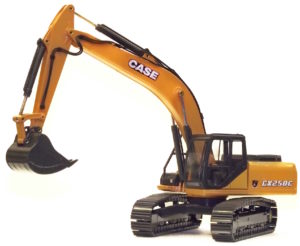
84402826: CX250C, CX250C LR Tier 4 Service Manual
MAKE: Case
MODEL: CX250C, CX250C LR Tier 4 Crawler Excavators
FORMAT: PDF
PAGES / SIZE: 1,897
“Case CX C Series Excavator Service Training Manual” – 1,441 pages
Complete digital official shop manual contains service, maintenance, and troubleshooting information for the Case CX250C, CX250C LR Crawler Excavators. Diagnostic and repair procedures are covered in great detail to repair, maintain, rebuild, refurbish or restore your Case CX250C, CX250C LR Crawler Excavator like a professional mechanic in local service/repair workshop. This cost-effective quality manual is 100% complete and intact as should be without any missing pages. It is the same factory shop manual used by dealers that guaranteed to be fully functional to save your precious time.
This manual for Case CX250C, CX250C LR Crawler Excavators is divided into different sections. Each section covers a specific component or system and, in addition to the standard service procedures, includes disassembling, inspecting, and assembling instructions. A table of contents is placed at the beginning of each section. Pages are easily found by category, and each page is expandable for great detail. It is in the cross-platform PDF document format so that it works like a charm on all kinds of devices. You do not need to be skilled with a computer to use the manual.
EXCERPT:
Electrical and Engine Basic Functions
Maintenance
Anti-theft
Enabling the anti-theft function
With the key OFF, connect the anti-theft knob terminal.
When the male and female knob terminals are connected on the cab main harness in the rear cover, the anti-theft
function is enabled.
The factory setting is for these knob terminals to be disconnected.
Anti-theft setting knob Connect VG (purple I green) and BG (black I green)
Password
Purpose
Locks the machine if is operated without authorization. (Anti-theft)
Operation explanation
1. When the anti-theft function is ON, turn the key ON.
2. Enter the correct password at the password input screen.
* If an incorrect password is input, “ERROR” is displayed and the buzzer buzzes.
If the correct password is then input, the lock is released.
3. The machine lock is released and the normal screen is displayed.
* If the “ERROR” message is ignored and the engine is started, the machine will lock.
Machine lock conditions
• The engine speed is fixed at low idle.
• The swing brake cannot be released .
• The travel alarm buzzes continuously.
* In addition, if the operator tries to operate the machine in the machine lock state, the engine will be stopped
Machine operation judgment conditions
• The P1 or P2 pressure rises to 5 MPa or higher
• The engine load ratio is 50% or higher for 2 sec. cumulative.
• The upper, travel, P1, or P2 pressure sensor is removed.
Immobilizer Key
Purpose
Prevents starting of the engine with keys other than the designated key. (Anti-theft)
Operation explanation
• When the key is switched ON, the immobilizer computer performs verification of the key.
If the key is verified as the designated key, cranking is performed.
If the key is not verified as the designated key, cranking is not performed.
* At this time, cranking will not be performed even if the key is turned up to ST.
Feed Pump Automatic Stop
Summary
The feed pump power supply is controlled and when the fuel tank is full (Level 8), the fuel feed is automatically stopped.
Configuration
Operation explanation
The fuel pump rocker switch has three positions: Manual, OFF, and Auto .
• Auto mode
The switch is the toggle type \1\/hen it comes ON, the fuel feed starts.
When the fuel tank angle sensor reaches the full level (Level 8), the monitor relay is driven and the feed pump power is switched OFF.
In place of that, the relay buzzes the buzzer to announce that the automatic feed has ended.
To silence the buzzer, the rocker switch must be switched to OFF or Manual.
• Manual mode
The switch is the momentary type The feed pump only drives fuel feed while the switch is pressed.
Coolant Level Drop
Summary
If the engine coolant level drops, the low coolant level warning is issued.
Configuration
Operation
1. The radiator reserve tank level switch is detected and an warning is issued.
• SW ON: 0.33- 0.53 L
Monitor
Buzzer
2. When the monitor receives the level drop signal, it carries out the following operation.
• Message “LOW COOLANT” is displayed.
Even after the coolant level is restored to normal, the “LOW COOLANT” message remains displayed while the key is ON.
• Diagnostic Trouble Code: “7423” is displayed.
Even after the coolant level is restored to normal, the “LOW COOLANT” message remains displayed while the key is ON.
• Monitor buzzer: The buzzer sounds at the same time that the message is displayed and the buzzer automatically stops after 5 sec.
3. When 3 sec. have passed after the coolant level switch was detected going OFF, the low coolant level alarm stops, the “LOW COOLANT” message goes off, and the buzzer stops.
…

