INSTANT DOWNLOAD (add to cart)
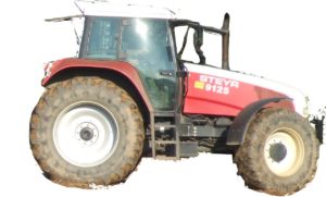
Case/Steyr 9000-Series Tractors Factory Service & Shop Manual

total 3,086 pages, bookmarked, Searchable, Printable, high quality PDF
“7-96100”
Case Steyr M9078, M9086, M9094 Tractors Service – Training Manual
SVA 7-96101; 161 MB PDF
CASE / CNH / STEYR: 9105, 9115, 9125, 9145, CS68, CS75, CS78, CS78a, CS86, CS86a, CS94, CS94a, CS100, CS110, CS120, CS130, CS150, M968, M975, M9078, M9078a, M9086, M9086a, M9094, M9094a, WD320, WD420
“7-96211”
CNH Österreich 9105, 9115, 9125, 9145 Tractors Service – Training Manual
SVA 7-96212; 233 MB PDF
CASE / CNH / STEYR: 9105, 9105a, 9115, 9115a, 9125, 9125a, 9145, 9145a, CS68, CS75, CS78, CS86, CS94, CS100, CS110, CS120, CS130, CS150
Complete workshop & service manual with electrical wiring diagrams for CNH/Case Steyr olde 9000 Series Tractors. It’s the same service manual used by dealers that guaranteed to be fully functional and intact without any missing page.
This CNH/Case Steyr 9000-Series Tractors (9105, 9105a, 9115, 9115a, 9125, 9125a, 9145, 9145a, CS68, CS75, CS78, CS78a, CS86, CS86a, CS94, CS94a, CS100, CS110, CS120, CS130, CS150, M968, M975, M9078, M9078a, M9086, M9086a, M9094, M9094a, WD320, WD420) service & repair manual (including maintenance, overhaul, disassembling & assembling, adjustment, tune-up, operation, inspecting, diagnostic & troubleshooting…) is divided into different sections. Each section covers a specific component or system with detailed illustrations. A table of contents is placed at the beginning of each section. Pages are easily found by category, and each page is expandable for great detail. The printer-ready PDF documents work like a charm on all kinds of devices.
EXCERPT:
2. FLYWHEEL CASING
A. Fitting the flywheel casing
The flywheel casing is centered on the cylinder block by means of two sprung dowel pins. The flywheel casings, which are also available as a spare part, are supplied with the bore holes for the pins.
1. Clean the sealing surfaces between the cylinder block and flywheel housing.
2. Apply sealant (e.g. silicone) to the points shown in the figure.
3. Lift the flywheel casing to the correct position and insert all the bolts.
4. Centre the casing and fit the sprung dowel pins using a mandrel.
5. Tighten the inner ring bolts to a torque of 60 Nm and the outer ring bolts to a torque of 110 Nm.
B. Replacing the rear crankshaft sealing ring
1. Separate the tractor between the engine and power unit.
2. Remove the flywheel.
3. Remove the sealing ring without damaging the crankshaft.
4. Clean the sealing ring seat and grind any burr.
NOTE: If the crankshaft is worn at the sealing ring seat, a 2 mm spacer ring (spare part number 162000020718 can be fitted behind the crankshaft sealing ring.
5. Carefully press the sealing ring in down to the bottom of the flywheel casing using the 1TSW 521 and 1TSW 662 fitting tools.
NOTE: THE ASSEMBLY PROCEDURE MUST BE CARRIED OUT IN A DRY AND OIL-FREE STATE.
…
