INSTANT DOWNLOAD
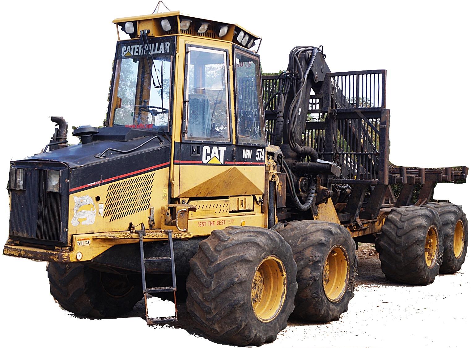
Complete workshop & service manual with electrical wiring diagrams for Caterpillar Forwarder 554 & 574. It’s the same service manual used by dealers that guaranteed to be fully functional and intact without any missing page.
This Caterpillar Forwarder 554 & 574 service & repair manual (including maintenance, overhaul, disassembling & assembling, adjustment, tune-up, operation, inspecting, diagnostic & troubleshooting…) is divided into different sections. Each section covers a specific component or system with detailed illustrations. A table of contents is placed at the beginning of each section. Pages are easily found by category, and each page is expandable for great detail. The printer-ready PDF documents work like a charm on all kinds of devices.
MANUAL LIST:
RENR6058 – Schematic (574 Forwarder Hydraulic System).pdf
RENR3025 – Disassembly & Assembly (554 Forwarder & 574 Forwarder Machine Systems)
RENR3026 – Specifications (554 & 574 Forwarders Power Train)
RENR3027 – Systems Operation (554 Forwarder & 574 Forwarder Power Train)
RENR3029 – Specifications (554 Forwarder & 574 Forwarder Hydraulic System)
RENR3030 – Systems Operation (554 Forwarder & 574 Forwarder Hydraulic System)
RENR3031 – Testing & Adjusting (554 Forwarder & 574 Forwarder Hydraulic System)
RENR3032 – Schematic (554 Forwarder Hydraulic System)
RENR3033 – Disassembly & Assembly (554 Forwarder & 574 Forwarder Power Train)
RENR3038 – Disassembly & Assembly (574 Forwarder Engine Supplement)
RENR3061 – Schematic (574 Forwarder Hydraulic System)
RENR3037 – Systems Operation (554 Forwarder & 574 Forwarder Electrical System).pdf
…
EXCERPT:
Disassembly Procedure
Start By:
A. Remove the implement control valve from the machine. Refer to Disassembly and Assembly, “Control Valve (Implement) – Remove” for the machine that is being serviced.
Note: Cleanliness is an important factor. Before the disassembly procedure, the exterior of the component should be thoroughly cleaned. This will help to prevent dirt from entering the internal mechanism.
1. Remove two screws and lock washers (1) from solenoid (2). Remove solenoid (2) from the control valve.
…