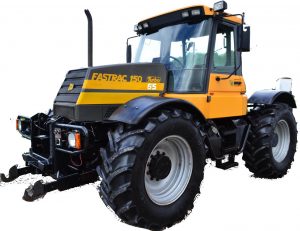
JCB Fastrac 125, 135, 145, 150, 155, 185
Complete workshop & service manual with electrical wiring diagrams for 135, 155, 175, 190, 205, 150T, 190T, 205T Skid Steer Small Platform. It’s the same service manual used by dealers that guaranteed to be fully functional and intact without any missing page.
This JCB 135, 155, 175, 190, 205, 150T, 190T, 205T Skid Steer Small Platform service & repair manual (including maintenance, overhaul, disassembling & assembling, adjustment, tune-up, operation, inspecting, diagnostic & troubleshooting…) is divided into different sections. Each section covers a specific component or system with detailed illustrations. A table of contents is placed at the beginning of each section. Pages are easily found by category, and each page is expandable for great detail. The printer-ready PDF documents work like a charm on all kinds of devices.
9813-1350-2 – 135, 155, 175, 190, 205, 150T, 190T, 205T Skid Steer Small Platform Service Manual
EXCERPT:
Skid Steer Small Platform
Service Manual – Skid Steer Small Platform
Section 1 – General Information
Section 2 – Care and Safety
Section 3 – Maintenance
Section A – Attachments
Section B – Body and Framework
Section C – Electrics
Section E – Hydraulics
Section F – Transmission
Section J – Tracks
Section K – Engine
…
Removal and Replacement
Removal
Note: Only the left-hand (L.H.) joystick is shown in the illustration K Fig 2. ( T E-53). The other joystick is removed and replaced in the same way.
Ensure that the engine is stopped and all hydraulic pressure is released from the system.
!MWARNING
It is not possible to vent all residual pressure. Loosen the connection one full turn and allow the pressure to dissipate. Keep face and hands well clear of
pressurised hydraulic oil and wear protective glasses.
HYD-4-3
Remove the covers from around the joystick body.
Mark the joystick flange and supporting flange to ensure correct realignment on replacement.
Label then remove hydraulic hoses and plug exposed connections to prevent ingress of dirt and water.
Disconnect the electrical connection if fitted.
Remove four screws 1 and washers 2, lift the joystick unit clear.
Replacement
Replacement is a reversal of the removal procedure.
Torque tighten hydraulic connections to 30 Nm (22 lbf ft).
Torque tighten screws 1 (4 off) to 10 Nm (7 lbf ft).
Reconnect the electrical connection if fitted. Replace covers around the joystick body.
…