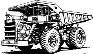
Pages from DG611 – Dump Truck 325M Shop Manual
Complete workshop & service manual with electrical wiring diagrams for Komatsu Dump Truck 325M. It’s the same service manual used by dealers that guaranteed to be fully functional and intact without any missing page.
This Komatsu Dump Truck 325M service & repair manual (including maintenance, overhaul, disassembling & assembling, adjustment, tune-up, operation, inspecting, diagnostic & troubleshooting…) is divided into different sections. Each section covers a specific component or system with detailed illustrations. A table of contents is placed at the beginning of each section. Pages are easily found by category, and each page is expandable for great detail. The printer-ready PDF documents work like a charm on all kinds of devices.
DG611 – Dump Truck 325M Shop Manual.pdf
EXCERPT:
TABLE OF CONTENTS
SUBJECT . . . . . . SECTION
GENERAL INFORMATION ……… A
STRUCTURES . . . . . . B
ENGINE, FUEL, COOUNG AND AIR CLEANER . . . . . . C
ELECTRIC SYSTEM (24 VDC. NON-PROPULSION) . . . . . . D
TRANSMISSION AND PTO . . . . . . F
DRIVE AXLE, SPINDLES AND WHEELS . . . . . . G
HYDRAIR® II SUSPENSIONS . . . . . . H
BRAKE CIRCUIT . . . . . . • • . J
AIR SYSTEM . . . . . . K
HYDRAULIC SYSTEM . . . . . . L
OPTIONS AND SPECIAL TOOLS . . . . . . M
OPERATOR’S CAB . . . . . . N
LUBRICATION AND SERVICE . . . . . . P
ALPHABETICAL INDEX . . . . . . Q
SYSTEM SCHEMATICS ……….. R
…
Disassembly
1. Remove capscrews and washers (9, Figure 3-3) and brake drum (8). The brake drum does not need to be removed unless repair or replacement is necessary.
2. Remove oil seal (20), spacer (4), bearing cone (21) and bearing cup (5).
3. Turn wheel hub over and remove bearing cup (12).
4. Remove seal runner (3) from spindle.
Cleaning and Inspection
1. Clean all metal parts in fresh cleaning solvent.
2. Replace any worn or damaged parts.
3. Replace 0-rings and seal runner if worn or damaged.
4. Inspect wheel hub and spindle for damage.
Spindle should be checked in area of inner radius for distress after seal runner has been removed.
Non destructive testing means can be used to check for possible cracks.
Assembly
1. Press bearing cup (12) into bore of wheel hub.
NOTE: Press bearings in using a hydraulic press with sufficient force to fully seat the bearing. Use a feeler gauge to check for gaps between bearing and shoulder. Bearings which are improperly seated can cause major repair problems.
2. Turn wheel hub over and press bearing cup (5) into bore of wheel hub.
3. Place bearing cone (21) into bearing cup (5).
4. Install spacer (4) and press oil seal (20) into wheel hub bore, using care not to damage the seal during assembly.
5. Install brake drum (8) on wheel hub if brake drum was removed.
6. Press seal runner (3) onto spindle.
…
