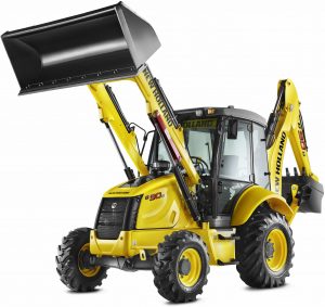
New Holland B90B, B90BLR, B100B, B100BLR, B100BTC, B110B, B110BTC, B115B
Complete workshop & service manual with electrical wiring diagrams for New Holland B90B, B90BLR, B100B, B100BLR, B100BTC, B110B, B110BTC, B115B. It’s the same service manual used by dealers that guaranteed to be fully functional and intact without any missing page.
This New Holland B90B, B90BLR, B100B, B100BLR, B100BTC, B110B, B110BTC, B115B service & repair manual (including maintenance, overhaul, disassembling & assembling, adjustment, tune-up, operation, inspecting, diagnostic & troubleshooting…) is divided into different sections. Each section covers a specific component or system with detailed illustrations. A table of contents is placed at the beginning of each section. Pages are easily found by category, and each page is expandable for great detail. The printer-ready PDF documents work like a charm on all kinds of devices.
FILELIST:
84428663A – B90B, B90BLR, B100B, B100BLR, B100BTC, B110B, B110BTC, B115B Backhoe Loaders Service Manual.pdf
84428663A1 – B90B, B90BLR, B100B, B100BLR, B100BTC, B110B, B110BTC, B115B Backhoe Loaders Service Manual.pdf
87643846B – B90B, B90BLR, B100B, B100BLR, B110B, B115B Backhoe Loaders Service Manual.pdf
“84428663A1.pdf”
New Holland Backhoe Loaders B90B, B90BLR, B100B, B100BLR, B100BTC, B110B, B110BTC, B115B Service Manual
Print No. 84428663A1
1,280 pages
SERVICE MANUAL
The Service Manual consists of two volumes:
– B90B – B90BLR – B100B – B100BLR – B100BTC – B110B – B110BTC – B115B Service Manual for “Loader backhoe”
– B90B – B90BLR – B100B – B100BLR – B100BTC – B110B – B110BTC – B115B Service Manual for “Engine”
The Service Manuals for “Loader backhoe” and “Engine” contain the necessary technical information to carry out service and repair on machine and on engine, necessary tools to carry out those operations and information on service standard, on procedures for connection, disconnection, disassembly and assembly of parts.
The Service Manual which covers the loader backhoe models B90B – B90BLR – B100B – B100BLR – B100BTC – B110B – B110BTC – B115B consists of the following volumes, which can be identified by their print number as stated below:
Service Manual for “Loader backhoe” B90B – B90BLR – B100B – B100BLR – B100BTC – B110B – B110BTC – B115B “84428663A1”
Service Manual – “Engine” B90B – B90BLR – B100B – B100BLR – B100BTC – B110B – B110BTC – B115B “87659057A”
…
— — — — — — — — — — — — — — — — — — — — — — — —
“87643846B.pdf”
New Holland Backhoe Loaders B90B, B90BLR, B100B, B100BLR, B110B, B115B Service Manual
Print No. 87643846B; 1,110 pages
COMPLETE HANDBOOK FOR INSTRUCTIONS AND REPAIRS
The complete Service Manual consists of two volumes:
B90B – B90BLR – B100B – B100BLR – B110B – B115B Service Manual for “Loader backhoe”
B90B – B90BLR – B100B – B100BLR – B110B – B115B Service Manual “Engine”
The Service Manuals for “Loader backhoe” and “Engine” contain the necessary technical information to carry out service and repair on machine and on engine, necessary tools to carry out those operations and information on service standard, on procedures for connection, disconnection, disassembly and assembly of parts.
The complete Service Manual which covers the loader backhoe models B90B – B90BLR – B100B – B100BLR – B110B – B115B consists of the following volumes, which can be identified through their print number as stated below:
Service Manual – “Loader backhoe” B90B – B90BLR – B100B – B100BLR – B110B – B115B “87643846B”
Service Manual – “Engine” B90B – B90BLR – B100B – B100BLR – B110B – B115B “87659057A”
EXCERPT:
SECTION 25 – FRONT AXLES
Loosen and remove the two fastening screws (1) of the planetary carrier cover (3).
Remove the planetary carrier cover (3) from the wheel hub. Remove the O-ring (11).
Position the planetary carrier cover (3) onto a workbench and check its wear conditions.
If necessary, replace the gears as follows:
unscrew the screws (10) on every pin (P);
remove the washers (8) and (9);
extract the gears (6);
collect the bearings (5) and check their conditions; Z collect the washer (4).
NOTE: with the new gears it is advisable to assemble new needles.
Assembly
Position the planetary carrier cover (3) onto a workbench.
Insert the washers (4) and the gears (6) complete with needles (5) in the pins of the planetary gear carrier.
Assemble the washers (8) and fasten them with the pins (7).
Assemble the washers (9) and screw on the screws (10) and tighten them to a torque of 73 Nm (53.84 lbf·ft).
NOTE: with the new gears it is advisable to assemble new needles.
Insert a new O-ring (11).
Assemble the epicyclic reduction gear assy onto the wheel hub.
Screw in the fastening screws (1) and tighten them to the prescribed torque of 25 Nm (18.43 lbf·ft).
Fill in oil into the reduction gear.
Screw in the plug (2) and tighten it to the prescribed torque of 60 Nm (44.25 lbf·ft).
…
