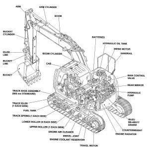
Complete workshop & service manual with electrical wiring diagrams for New Holland Kobelco E115SR, E135SR, E135BSR Crawler Excavator. It’s the same service manual used by dealers that guaranteed to be fully functional and intact without any missing page.
This New Holland Kobelco E115SR, E135SR, E135BSR Crawler Excavator service & repair manual (including maintenance, overhaul, disassembling & assembling, adjustment, tune-up, operation, inspecting, diagnostic & troubleshooting…) is divided into different sections. Each section covers a specific component or system with detailed illustrations. A table of contents is placed at the beginning of each section. Pages are easily found by category, and each page is expandable for great detail. The printer-ready PDF documents work like a charm on all kinds of devices.
“604.13.426.pdf”
New Holland Kobelco E115SR, E135SR Crawler Excavator Worksop Manual
996 pages
Print No. 604.13.426
Edition: 03/2005 English
“87743920A – New Holland_Kobelco E135BSR Repair Manual.pdf”
INDEX
SPECIFICATIONS
Section 1 – Outline
Section 2 – Specification
Section 3 – Attachment dimension
MAINTENANCE
Section 11 – Tools
Section 12 – Standard maintenance time schedule Section 13 – Maintenance standard and test procedure
SYSTEM
Section 21 – Mechatro control system Section 22 – Hydraulic system Section 23 – Electric system
Section 24 – Components system Section 25 – Air-conditioner system
DISASSEMBLING
Section 31 – Disassembling and assembling Section 32 – Attachment
Section 33 – Upper structure
Section 34 – Travel system
TROUBLESHOOTING
Section 41 – Troubleshooting (mechatro control) Section 42 – Troubleshooting (Hydraulic) Section 43 – Troubleshooting (Electric)
Section 44 – Troubleshooting (Engine)
ENGINE
Section 51 – Engine
OPT
Section 63 – Mounting the breaker and nibbler & breaker
…
…
— — — — — — — — — — — — — — — — — — — — —
EXCERPT:
4.2 REMOVAL AND INSTALLATION OF THE UNIT
(1) Removing the blower unit
1) Remove the connectors connected to the inner/outer air select motor actuator, the blower motor and the blower controller. Also remove the harness from the blower casing.
2) Draw out the inner air filter from the intake casing. Remove four cross-recessed screws T5×14 (T1) from the top of the intake casing, using a screwdriver. Then remove the intake casing.
3) Remove three cross-recessed screws T5×14 (T1) fastening the blower casing with the unit casing. Then separate the blower unit from the air-conditioner unit.
(2) Replacing the blower motor
1) Disconnect the cooling hose that is connected between the blower motor and the blower casing.
2) Remove three cross-recessed screws N5×16 (W) fixed from the bottom of the blower unit casing. Then draw out the blower motor.
Do not separate the fan from the blower motor.
3) Assembly is the reverse order of disassembly.
(3) Replacing the blower controller
1) Remove two cross-recessed screws T4×14 (T1) fixed from the bottom of the blower unit casing and draw out the blower controller.
2) Install a new blower controller in the reverse order of removal.
Do not disassemble the blower controller in any circumstances.
…
