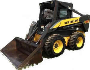
New Holland C185, C190, L180, L185, L190
Complete workshop & service manual with electrical wiring diagrams for New Holland L180, L185, L190 Skid Steer Loader, C185, C190, Compact Track Loader. It’s the same service manual used by dealers that guaranteed to be fully functional and intact without any missing page.
This New Holland L180, L185, L190 Skid Steer Loader, C185, C190, Compact Track Loader service & repair manual (including maintenance, overhaul, disassembling & assembling, adjustment, tune-up, operation, inspecting, diagnostic & troubleshooting…) is divided into different sections. Each section covers a specific component or system with detailed illustrations. A table of contents is placed at the beginning of each section. Pages are easily found by category, and each page is expandable for great detail. The printer-ready PDF documents work like a charm on all kinds of devices.
“84522361.pdf”
New Holland L180, L185, L190 Skid Steer Loader, C185, C190, Compact Track Loader Mechanical and Pilot Control (Cab Upgrade Machines) Repair Manual
87630288 NA Replaces 87578815 NA
Issued 12-2006 Revised 05-2007
1,068 pages
CONTENTS
INTRODUCTION
DISTRIBUTION SYSTEMS
PRIMARY HYDRAULIC POWER SYSTEM SECONDARY HYDRAULIC POWER SYSTEM HIGHFLOW HYDRAULIC POWER SYSTEM ELECTRICAL POWER SYSTEM
LIGHTING SYSTEM
POWER PRODUCTION ENGINE
FUEL AND INJECTION SYSTEM AIR INTAKE SYSTEM
ENGINE COOLANT SYSTEM LUBRICATION SYSTEM STARTING SYSTEM
POWER TRAIN
POWER COUPLING Fixed coupling
TRANSMISSION Hydrostatic
TRAVELLING
FRONT AXLE
REAR AXLE
STEERING Steering clutch
PARKING BRAKE Hydraulic
WHEELS AND TRACKS Tracks WHEELS AND TRACKS Wheels Final drive
BODY AND STRUCTURE USER CONTROLS AND SEAT USER PLATFORM
ENVIRONMENT CONTROL Heating system
ENVIRONMENT CONTROL Air-conditioning system SAFETY SECURITY ACCESSORIES Safety
WORKING ARM
SINGLE ARM Lift
SINGLE ARM TOOL ATTACHMENT Tilt
TOOLS AND COUPLERS CARRYING Unarticulated tools COUPLING Hydraulic coupling
COUPLING Mechanical coupling
…
— — — — — — — — — — — — — — — — — — — — — — — —
EXCERPT:
POWER TRAIN TRANSMISSION Hydrostatic
Pump Right hand pump Measure
1. Measure the free travel between the shoes and the pistons. If all the measurements are not equal to within 0.13 mm (0.005 in), use a new cylinder assembly.
2. Measure the thickness of each shoe. If the measurements are not equal to within 0.02 mm (0.0001 in), use a new cylinder assembly.
3. Check the fit of the pistons in the bores. The piston must move freely with minimum clearance. Use a new cylinder assembly as necessary.
4. Measure the gear tip clearance between the inner gear and the outer gear. Clearance must not be more than 0.13 mm (0.005 in).
5. Measure the width of the inner gear and the outer gear. The width of each gear must be equal to within 0.05 0.06 mm (0.002 0.003 in).
…
