Posted on

Case 580 Super E Loader Backhoe Workshop Repair & Service Manual


Download Link

INSTANT DOWNLOAD (add to cart)


1,472 pages, bookmarked, Searchable, Printable, high quality PDF

“Case 580 Super E (580SE) Service Manual.pdf”
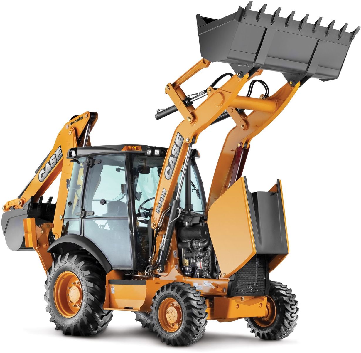
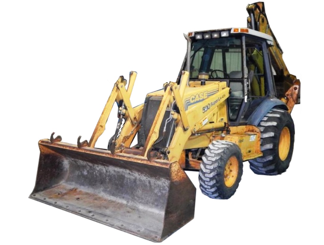
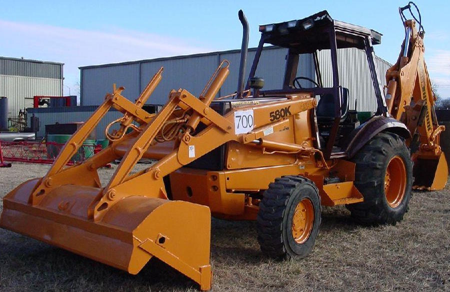
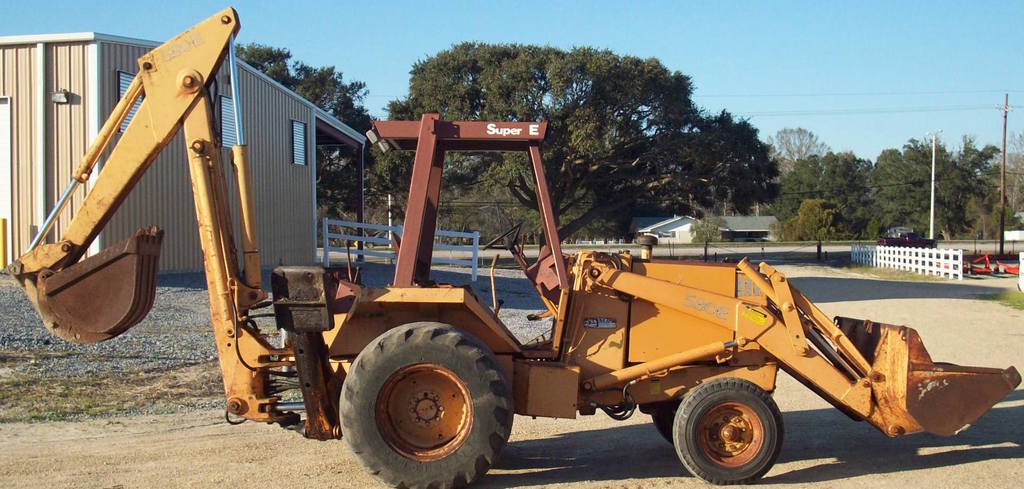
Case 580 Super E (580SE) Loader Backhoe Service Manual
1,472 pages

Complete digital official shop manual contains service, maintenance, and troubleshooting information for the Case 580 Super E (580SE) Loader Backhoe. Diagnostic and repair procedures are covered in great detail to repair, maintain, rebuild, refurbish or restore your 580SE like a professional mechanic in local service/repair workshop. This cost-effective quality manual is 100% complete and intact as should be without any missing pages. It is the same factory shop manual used by dealers that guaranteed to be fully functional to save your precious time.

This manual for Case 580 Super E Loader Backhoe is divided into different sections. Each section covers a specific component or system and, in addition to the standard service procedures, includes disassembling, inspecting, and assembling instructions. A table of contents is placed at the beginning of each section. Pages are easily found by category, and each page is expandable for great detail. It is in the cross-platform PDF document format so that it works like a charm on all kinds of devices. You do not need to be skilled with a computer to use the manual.

EXCERPT:
580 SUPER E LOADER BACKHOE
TABLE OF CONTENTS
SECTION NO.
Safety Rules, and Service Manual Introduction and Torque Specifications… 1001
Maintenance and Lubrication.. 1002
General Engine Specifications… 1010
Detailed Engine Specifications… 1024
2 ENGINES
Engine Stall Tests.. 2000
Engine Removal and Installation.. 2001
Engine Accessories (Air Cleaner, Muffler, Exhaust Pipe, Radiator, Cold Start System)… 2002
Cylinder Head and Valve Train.. 2415
Cylinder Block, Pistons, Rods, Camshaft, Main Bearings, Oil Seals, and Flywheel… 2425
Lubrication System.. 2445
Cooling System… 2455
Turbocharger.. 2465
Turbocharger Failure Analysis… 2565
3 FUEL SYSTEM
Engine Controls, Fuel Lines, and Fuel Tank… 3001
Fuel System and Filters.. 3410
Fuel Injection Pump and Drive Gear.. 3412
Fuel Injectors… 3413
4 ELECTRICAL
Electrical Specifications and Troubleshooting… 4002
Wiring Diagrams.. 4003
Battery… 4005
Starter and Starter Solenoid… 4006
Alternator… 4007
Instrument Cluster and Gauges.. 4009
5 STEERING
Steering System Troubleshooting.. 5002
Steering Control Valve and Steering Column.. 5007
Steering Cylinders… 5010
Front Axle- Two-Wheel Drive Machines.. 5021
Front Axle- Four-Wheel Drive Machines.. 5022
Steering Relief Valve.. See Section 8008
6 POWER TRAIN
Power Shuttle Maintenance, Operation, and Troubleshooting. 6202
Power Shuttle and Torque Converter… 6210
Power Shuttle Controls.. 6211
Transaxle Removal and Installation… 6212
Transaxle and Differential Lock… 6215
Transaxle and Differential Lock-Wet Brakes.. 6217
Transfer Gear Box… 6216
Driveshaft… 6222
Wheels and Tires.. 6229
7 BRAKES
Brake Pedals and Linkage, Master Cylinder, and
Parking Brake… 7106
Self-Adjusting Differential Brakes.. 7123
Differential Brakes- Wet Brakes… 7125
8 HYDRAULICS
Hydraulic Specifications, Maintenance, Troubleshooting, Flowmeter Tests, and Pressure Checks… 8002
Cleaning the Hydraulic System… 8003
Hydraulic Pump… 8005
Loader Control Valve Made by J.l. Case… 8006
Loader Control Valve Made by Parker Hannifin.. 8007
Steering Relief Valve and Quick Disconnect Couplings… 8008
Three Point Hitch Control Valves… 8009
Cylinders… 8090
Backhoe Control Valve.. 8107
Stabilizer Control Valve.. 8109
9 MOUNTED EQUIPMENT/CHASSIS
Air Conditioning Troubleshooting.. 9002
Air Conditioning System… 9003
Loader.. 9010
Three Point Hitch… 9033
ROPS Cab and ROPS Canopy.. 9061
Seats, Seat Belts, and Seat Supports.. 9064
Backhoe.. 9100
Decals and Painting… 9201

For maximum Loctite strength the following torque sequence must be followed.
1. Tighten bolts 1 and 2 by hand. Then tighten bolts 1 and 2, 1/2 turn at a time until a torque of 30 lb ft (41 Nm)(4.1 kgm) is reached.
2. Tighten each bolt (3 through 20) to a torque of 30 lb ft (41 Nm)(4.1 kgm) in the shown sequence.
3. Tighten the bolts 1 through 20 to a torque of 40 lb ft (54 Nm)(5.4 kgm) in the shown sequence.
4. Then loosen each bolt 1/4 turn (one at a time) in the sequence shown. Tighten to a torque of 50 to 55 lb ft (68 to 75 Nm)(6.8 to 7.5 kgm).
NOTE: Each bolt must be loosened and torqued before loosening the next bolt.
STEP 181
Press the cross shaft into the center-wheel until the smooth area between the splines is visible in the pinion gear mounting holes.
STEP 182
Install the pinion gears and pins.
NOTE: Make sure hole in the pin aligns with the center-wheel hole.
STEP 183
Install the pinion retaining groove pins to a depth of 0.12 inch (3.05 mm) below the center-wheel surface.
STEP 184
Use a hammer and center punch to secure the groove pins. This will prevent the groove pins from moving.
STEP 185
NOTE: Some of the Loader/Backhoe side gears have an identification mark cut in the center of spur gear. Replacement parts may not have an identification mark cut in the center of the side gear.
STEP 186
Apply Number 1 permatex to the 0.0. of a new cup plug.
STEP 187
Push the cup plug into the LH side gear until the plug makes contact in the gear bore.
..I

Posted on

Case 580N/580SN/580SN-WT/590SN Workshop Repair & Service Manual


Download Link

INSTANT DOWNLOAD (add to cart)


Case 580N/580SN/580SN-WT/590SN Workshop Repair & Service Manual

6,600+ pages, bookmarked, Searchable, Printable, high quality PDF

MAKE: Case
MODEL: 580N, 580SN, 580SN-WT, 590SN Tractor Loader Backhoe
FORMAT: PDF
PAGES / SIZE: PDF (902 MB)

“47365539.pdf”
3,501 pages
580N, 580SN WT (580 Super N WT), 580SN, 590SN Service Manual
47365539 08/07/2012

“84261053.pdf”
580N, 580SN-WT, 580SN, 590SN Loader Backhoe Operator’s Manual
330 pages
Part number 84482502
2nd edition English
October 2011
Replaces part number 84261053

“84516378.pdf”
580N, 580SN-WT, 580SN, 590SN Tractor Loader Backhoe Service Manual
2,895 pages
Part number 84516378
English
July 2011
Replaces part number 84390833

“84540378.pdf”
151 pages
ENGINE AND PTO IN – B
580N, 580SN-WT, 580SN, 590SN Tractor Loader Backhoe Service Manual
Part number 84540378
English
July 2011
Replaces part number 84393971

Complete digital official shop manual contains service, maintenance, and troubleshooting information for the for Case 580N, 580SN, 580SN-WT, 590SN Tractor Loader Backhoe. Diagnostic and repair procedures are covered in great detail to repair, maintain, rebuild, refurbish or restore your Case 580N/580SN/580SN-WT/590SN like a professional mechanic in local service/repair workshop. This cost-effective quality manual is 100% complete and intact as should be without any missing pages. It is the same factory shop manual used by dealers that guaranteed to be fully functional to save your precious time.

This manual for Case 580N, 580SN, 580SN-WT, 590SN Tractor Loader Backhoe is divided into different sections. Each section covers a specific component or system and, in addition to the standard service procedures, includes disassembling, inspecting, and assembling instructions. A table of contents is placed at the beginning of each section. Pages are easily found by category, and each page is expandable for great detail. It is in the cross-platform PDF document format so that it works like a charm on all kinds of devices. You do not need to be skilled with a computer to use the manual.

EXCERPT:
Contents
INTRODUCTION
HYDRAULIC, PNEUMATIC, ELECTRICAL, ELECTRONIC SYSTEMS A
PRIMARY HYDRAULIC POWER SYSTEM … A.10.A
SECONDARY HYDRAULIC POWER SYSTEM.. A.12.A
ELECTRICAL POWER SYSTEM .. A.30.A
FAULT CODES … . A.50.A
ENGINE AND PTO IN … B
ENGINE .. . B.10.A
FUEL AND INJECTION SYSTEM.. B.20.A
EXHAUST SYSTEM… . B.40.A
ENGINE COOLANT SYSTEM .. . B.50.A
STARTING SYSTEM … . B.80.A
TRANSMISSION, DRIVE AND PTO OUT … C
TRANSMISSION Power Shuttle.. . C.20.C
TRANSMISSION Power-shift .. . C.20.E
AXLES, BRAKES AND STEERING.. D
FRONT AXLE … . D.10.A
REAR AXLE .. D.12.A
STEERING Hydraulic… . D.20.C
SERVICE BRAKE Hydraulic.. . D.30.C
PARKING BRAKE Mechanical .. . D.32.B
WHEELS AND TRACKS Wheels.. . D.50.C
FRAME AND CAB … E
FRAME Primary frame … E.10.B
SHIELD .. . E.20.A
USER CONTROLS AND SEAT .. . E.32.A
USER CONTROLS AND SEAT Operator seat .. . E.32.C
USER PLATFORM …E.34.A
ENVIRONMENT CONTROL Air-conditioning system .. . E.40.C
FRAME POSITIONING .. F
STABILIZING Working stabilizing .. F.20.D
TOOL POSITIONING … G
LIFTING .. . G.10.A
HITCH AND WORKING TOOL .. H
BOOM Lift .. . H.20.B
BOOM Swing …H.20.D
DIPPER Lift.. . H.25.B
DIPPER Extension … . H.25.F
ARM TOOL ATTACHMENT Tilt.. . H.30.C
EXCAVATING AND LANDSCAPING … J
DIGGING Non-articulated digging tools … . J.20.B
CARRYING Articulated tools .. . J.50.C

TRANSMISSION, DRIVE AND PTO OUT – TRANSMISSION Power Shuttle
TRANSMISSION Power Shuttle – Test – Checking Differential Lock Valve
CAS-1804 Pressure Test Kit
CAS-1808 Flowmeter Fitting Kit
NOTE: See TRANSMISSION Power Shuttle – Tool connection Two Wheel Drive Port Identification (C.20.C) or TRANSMISSION Power Shuttle – Tool connection Four Wheel Drive Port Identification (C.20.C) for test port locations.
1. Engage the parking brake.
2. Place the transmission in neutral.
3. Start the engine. The oil should be at normal operating temperatures.
4. Connect a pressure test fitting and a 42 bar (600 psi) gauge to test port 7 (A).
5. With the transmission shift lever in Neutral, put the directional control lever in Forward or Reverse.
6. Run the engine at 2200 RPM.
7. Press and hold the differential lock switch located in the loader control valve.
8. Monitor the gauge and record the values for low idle, see TRANSMISSION Power Shuttle – Pressure test – 2 Wheel Drive, Test One — Engine at Idle 900 to 1100 rpm (C.20.C) or TRANSMISSION
Power Shuttle – Pressure test – 4 Wheel
Drive, Test One — Engine at Idle 900 to 1100 rpm (C.20.C).
9. Monitor the gauge and record the values for full throttle, see TRANSMISSION Power Shuttle – Pressure test — 2 Wheel Drive, Test Two — Engine at 2200 rpm (C.20.C) or TRANSMISSION Power Shuttle –
Pressure test — 4 Wheel Drive, Test Two — Engine at 2200 rpm (C.20.C).

Posted on

Case 580M, 580M Turbo, 580 Super M, 580 Super M+, 590 Super M, 590 Super M+ Loader Factory Service & Shop Manual


Download Link

INSTANT DOWNLOAD (add to cart)


Complete workshop & service manual with electrical wiring diagrams for Case M Series 1/2/3 Loader Backhoe. It’s the same service manual used by dealers that guaranteed to be fully functional and intact without any missing page.

This Case 580M, 580M Turbo, 580 Super M, 580 Super M+, 590 Super M, 590 Super M+ Loader service & repair manual (including maintenance, overhaul, disassembling & assembling, adjustment, tune-up, operation, inspecting, diagnostic & troubleshooting…) is divided into different sections. Each section covers a specific component or system with detailed illustrations. A table of contents is placed at the beginning of each section. Pages are easily found by category, and each page is expandable for great detail. The printer-ready PDF documents work like a charm on all kinds of devices.

8,600+ pages, bookmarked, Searchable, Printable, high quality PDF

“6-41490.pdf”
Case M Series Loader / Backhoe Service Manual; 6-41490; 366 MB; 1,524 pages
Case Series 580M, 580 Super M (580SM) , 590 Super M (590SM) Loader / Backhoe

— — — — — — — — — — — — — — — — — — — — — — — — — — — — — — — — —

“6-74432.pdf”
Case M Series 2 Loader / Backhoe Service Manual; Bur 6-74432; 703 MB; 1,713 pages
Case Series 2 580M, 580M Turbo, 580 Super M (580SM), 580 Super M+ (580SM+), 590 Super M (590SM) Loader / Backhoe

— — — — — — — — — — — — — — — — — — — — — — — — — — — — — — — — —

“87728449NA.pdf”
Case M Series 3 Loader / Backhoe Service Manual; Bur 6-74432; 284 MB; 1,467 pages
Case 580M, 580 Super M (580SM), 580 Super M+ (580SM+), 590 Super M (590SM), 590 Super M+ (590SM+) Series 3 Loader / Backhoe

— — — — — — — — — — — — — — — — — — — — — — — — — — — — — — — — —

“6-75122.pdf”
Electrical Schematic & Hydraulic Schematic for 580M, 580SM, 580SM+, 590SM Series 2 Loader Backhoe

— — — — — — — — — — — — — — — — — — — — — — — — — — — — — — — — —

“5-12380.pdf”
Electrical Schematic & Hydraulic Schematic for 580M, 580SM, 580SM+, 590SM, 590SM+ Series 3 Loader Backhoe

— — — — — — — — — — — — — — — — — — — — — — — — — — — — — — — — —

“6-20601.pdf”
580M, 580M Turbo, 580 Super M, 590 Super M Series Loader Backhoe Operator’s Manual; 315 pages

— — — — — — — — — — — — — — — — — — — — — — — — — — — — — — — — —

“87592031.pdf”
580M, 580M Turbo, 580 Super M, 580 Super M+, 590 Super M Series 2 Loader Backhoe Operator’s Manual; 304 pages

— — — — — — — — — — — — — — — — — — — — — — — — — — — — — — — — —

“84287120.pdf”
580M, 580 Super M, 580 Super M+, 590 Super M, 590 Super M+ Series 3 Loader Backhoe Operator’s Manual; 263 pages

— — — — — — — — — — — — — — — — — — — — — — — — — — — — — — — — —

“87657943NA.pdf”
Series 3 Loader Backhoe Operator’s Manual; 260 pages
580M, 580 Super M, 580 Super M+, 590 Super M, 590 Super M+ Series3 Tier 3 3 Loader Backhoe

— — — — — — — — — — — — — — — — — — — — — — — — — — — — — — — — —

“7-6091 NA.pdf”
580 Super M Loader Backhoe Parts Catalog; 808 pages

— — — — — — — — — — — — — — — — — — — — — — — — — — — — — — — — —

“7-9043 NA.pdf”
580 Super M, 580 Super M+ Series 2 Loader Backhoe Parts Catalog; 982 pages; 7-9043 NA, Replaces 7-9042 NA

— — — — — — — — — — — — — — — — — — — — — — — — — — — — — — — — —

“87632284NA.pdf”
580 Super M, 580 Super M+ Series 3 Loader Backhoe Parts Catalog; 930 pages

— — — — — — — — — — — — — — — — — — — — — — — — — — — — — — — — —

EXCERPT:
SECTION INDEX
POWER TRAIN
Removal and Installation of Power Train Components . . . . . . . . . . . . . . . . . .6000
Standard Transmission Specifications, Pressure Checks, and Troubleshooting . . . . . . . . . . . . . . . . . . . . . . . .6002
Power Shift Transmission Specifications, Pressure Checks and Troubleshooting . . . . . . . . . . . . . . . . . . . . . . .6002
Wheels and Tires . . . . . . . . . . . . . . . . . . . . . . . . . . . . . .6003
Rear Axle and Planetaries – 580M and 580SM . . . . . . . . . . . . . . . . . . . . . . . .6004
Rear Axle and Planetaries – 580SM+, 590SM and 590SM+ . . . . . . . . . . . . . .6004
Standard Transmission . . . . . . . . . . . . . . . . . . . . . . . . . . . . . . . . . . . . . . . . . .6007
Power Shift Transmission . . . . . . . . . . . . . . . . . . . . . . . . . . . . . . . . . . . . . . . .6007

MANUAL TRANSMISSION
Removal
STEP 1
Park the machine on a level surface. Put the backhoe in the transport position with the stabilizers down. Also put the loader bucket on the floor.
STEP 2
Raise the wheels off the floor high enough to remove the transmission. Put suitable stands under both sides of the machine at the front and rear.
NOTE: The rear wheels can be removed to ease the transmission removal.
STEP 3
Drain the transmission oil.
STEP 4
Disconnect the supply line (1) from the transmission,
disconnect the return line (2) from the transmission.
STEP 5
Disconnect the differential lock hose.
STEP 6
1. FRONT CAB FLOOR MAT
2. CAB FRONT FLOOR PLATE
If equipped, remove the front cab floor mat (1).
Remove the cab front floor plate (2).
STEP 7
1. RETURN SPRING
2. TRANSMISSION GEAR SHIFT LEVER
3. TRANSMISSION SHIFTER MECHANISM
Disconnect the return spring (1) for the shift lever.
Disconnect the transmission gear shift lever (2) from the transmission shifter mechanism (3).
STEP 8
Disconnect the wiring harness connector for the transmission shift solenoid.
STEP 9
Disconnect the wiring harness for the transmission temperature sender.
STEP 10
Disconnect the wiring harness for the SAHR parking brake.
STEP 11
If equipped, disconnect the wiring harness for the four wheel drive solenoid.
STEP 12
Loosen and remove the cap screw and washer (1) for the left rear mounting bracket on front drive shaft guard through the access hole in the fuel tank.
STEP 13
Loosen and remove the bolts, washers, and nuts (2) that fasten the left rear mounting bracket to front drive shaft guard. Remove the left rear mounting bracket.

Posted on

Case 580L, 580 Super L, 590L, 590 Super L Factory Service & Shop Manual


Download Link

INSTANT DOWNLOAD (add to cart)


Complete workshop & service manual with electrical wiring diagrams for Case 580L, 580 Super L, 590L, 590 Super L. It’s the same service manual used by dealers that guaranteed to be fully functional and intact without any missing page.

This Case 580L, 580 Super L, 590L, 590 Super L service & repair manual (including maintenance, overhaul, disassembling & assembling, adjustment, tune-up, operation, inspecting, diagnostic & troubleshooting…) is divided into different sections. Each section covers a specific component or system with detailed illustrations. A table of contents is placed at the beginning of each section. Pages are easily found by category, and each page is expandable for great detail. The printer-ready PDF documents work like a charm on all kinds of devices.

1,702+1,468 pages, bookmarked, Searchable, Printable, high quality PDF

EXCERPT:
MASTER CYLINDER
Removal
STEP 1
Park the machine on a level surface. Raise the loader and lock the support strut to hold the loader.
STEP 2
Apply the parking brake.
STEP 3
Open the hood.
STEP 4
Loosen the clamp for the exhaust pipe at the muffler.
Remove the exhaust pipe from the muffler.
STEP 5
Remove the tie strap (1 ). Disconnect the electrical connectors (2) for the air restriction indicator. Loosen
the clamp (3) on the air cleaner hose. Disconnect the hose from the air cleaner.
STEP 6
Remove the cap screws and flat washers that fasten the cover to the uprights. Remove the cover and air cleaner as an assembly.
STEP 7
Remove the bolts, flat washers, and insulator curtain that covers the master cylinders.
NOTE: See the illustration on page 6 for the following steps.
STEP 8
Remove any dirt from the master cylinder (1) and the area around the master cylinder (1).

Posted on

Case 580K Loader Backhoe Workshop Repair & Service Manual


Download Link

INSTANT DOWNLOAD (add to cart)


Complete digital official shop manual contains service, maintenance, and troubleshooting information for the Case 580K Loader Backhoe. Diagnostic and repair procedures are covered in great detail to repair, maintain, rebuild, refurbish or restore your Case 580K Loader Backhoe like a professional mechanic in local service/repair workshop. This cost-effective quality manual is 100% complete and intact as should be without any missing pages. It is the same factory shop manual used by dealers that guaranteed to be fully functional to save your precious time.

This manual for Case 580K Loader Backhoe is divided into different sections. Each section covers a specific component or system and, in addition to the standard service procedures, includes disassembling, inspecting, and assembling instructions. A table of contents is placed at the beginning of each section. Pages are easily found by category, and each page is expandable for great detail. It is in the cross-platform PDF document format so that it works like a charm on all kinds of devices. You do not need to be skilled with a computer to use the manual.

2,700+ pages, bookmarked, Searchable, Printable, high quality PDF

FILE LIST:
“580K Phase 1 Service Manual.pdf”
1,290 pages; Bur 8-71551

“580K Phase 3 Service Manual.pdf”
1,447 pages; 8-12790

“580K Phase 1 Operator’s Manual.pdf”
192 pages; 9-11593

“580K Phase 1 Operator’s Manual.pdf”
221 pages; 9-15981

EXCERPT:
7003-4
Inspection
1. Inspect the bores in the body (6) for scoring, pitting, or other damage. If the bores in the body (6) are damaged a new master cylinder must be used.
2. Check the tab in the spring seat (12). Push the tab down a small amount so that the tab will engage the end of the piston (8) to hold the check valve assembly in place. If the tab is broken, use a new master cylinder.
3. Inspect the flow valve (3), ball (5), check valve piston (8), piston (13), and the push rod (15) for scoring, pitting, or other damage. If the flow valve (3), ball (5), check valve piston (8), piston (13) or the push rod (15) are damaged a new master cylinder must be used.
Assembly
1. Install the check valve seal (7) on the check valve piston (8).
2. Install the spring (11) on the spring seat (1 0).
3. Install the check valve assembly in the spring (11). Engage the stem of the check valve piston (8) in the spring seat (12).
4. Install the check valve assembly on the piston (13). Push the check valve assembly onto the piston (13) until the tab in the spring seat (12) engages the end of the piston (13).
5. Install the seal (14) on the piston (13).
6. Lubricate the bore of the body (6) with clean hydraulic fluid.
7. Install the piston assembly into the bore of the body (6).
8. Push the piston assembly into the bore until the push rod (15) and washer (16) can be installed.
9. Install the push rod (15) and washer (16).
10. Install the snap ring (17).
11. Install the boot (18).
12. Install the lock nut and clevis on the push rod (15). Do not tighten the lock nut on the push rod at this time.
13. Install the ball (5) in the body (6).
14. Lubricate the flow valve seal (4) and the flow valve (3) with clean hydraulic oil. Install the flow valve (3) in the bore in the master cylinder. The flow valve (3) must be centered in the bore of the master cylinder.
15. Install a new gasket (2) on the flow valve adapter (1).
16. Carefully start the flow valve adapter (1) into the bore in the master cylinder by hand. If the flow valve adapter (1) cannot be turned into the master cylinder completely by hand remove the flow valve adapter (1) from the master cylinder and make sure that the flow valve (3) is in the center of the bore in the master cylinder.
17. Repeat step 16 until the flow valve adapter (1) can be turned completely into the master cylinder by hand.
18. Tighten the flow valve adapter (1) to 30 to 34 pound-feet (41 to 47 Nm).
19. See Section 7002 and install the master cylinder on the machine.
20. Depress the brake pedal to stroke the piston (13) in the master cylinder. Release the brake pedal and allow the piston to return. Adjust the push rod to piston clearance to .025 to .050 inch (0.6 to 1.3 mm). Turn the clevis clockwise to shorten or counterclockwise to lengthen.
Tighten the lock nut against the clevis. See the illustration below. 0.025 to 0.05 INCH (0.6 to 1.3 mm)