Posted on

Case 580D Loader Backhoe Workshop Repair & Service Manual


Download Link

INSTANT DOWNLOAD (add to cart)


Complete digital official shop manual contains service, maintenance, and troubleshooting information for the Case 580D Loader Backhoe. Diagnostic and repair procedures are covered in great detail to repair, maintain, rebuild, refurbish or restore your Case 580D like a professional mechanic in local service/repair workshop. This cost-effective quality manual is 100% complete and intact as should be without any missing pages. It is the same factory shop manual used by dealers that guaranteed to be fully functional to save your precious time.

This manual for Case 580D Loader Backhoe is divided into different sections. Each section covers a specific component or system and, in addition to the standard service procedures, includes disassembling, inspecting, and assembling instructions. A table of contents is placed at the beginning of each section. Pages are easily found by category, and each page is expandable for great detail. It is in the cross-platform PDF document format so that it works like a charm on all kinds of devices. You do not need to be skilled with a computer to use the manual.

1,766+ pages, bookmarked, Searchable, Printable, high quality PDF

“Service Manual.pdf”
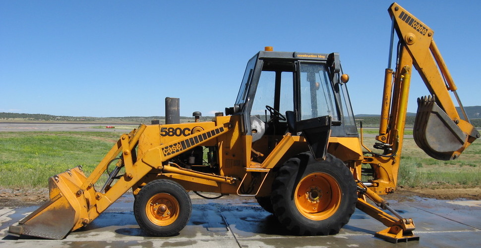
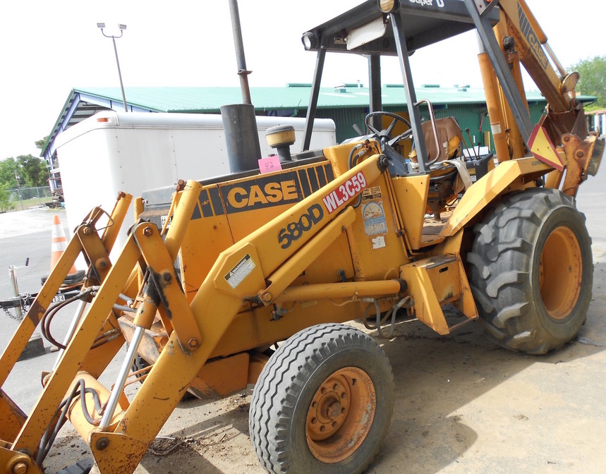
Case 580D Loader Backhoe Service Manual
1,766 pages

“Operator’s Manual.pdf”
Case 580D Loader Backhoe Operator’s Manual
28 pages

EXCERPT:
5800 LOADER BACKHOE
TABLE OF CONTENTS
DIVISION/SECTION SECTION NO.
1- GENERAL
Service Manual Introduction … 1001
Maintenance and Lubrication … 1002
General Engine Specifications- 207 Naturally Aspirated Engine … 10t0
Detailed Engine Specifications- 207 Naturally Aspirated Engine … 102-6
General Engine Specifications- 207 Turbocharged Engine … 1210
Detailed Engine Specifications – 207 Turbocharged Engines … 122e
2- ENGINES
Engine Diagnosis … 2001
Engine Tune-Up- 207 Naturally Aspirated Engine … 2002
Engine Stall Tests … 2003
Engine Removal and Installation … 2004
Engine Accessories (Air cleaners, muffler, exhaust pipe, radiator, turbocharger removal and installation, cold start system) … 2005
207 NATURALLY ASPIRATED ENGINE
Cylinder Head, Valve Train, and Camshaft … 2015
Crankshaft, Bearings, Flywheel, and Oil Seals … 2035
Oil Pump … 2045
Cooling System … 2055
Cylinder Block, Sleeves, Pistons, and Rods … 2125
Lubrication System (See Section 2555) 207 TURBOCHARGED ENGINE Engine-Tune-Up … 2202
Cylinder Head, Valve Train, and Camshaft … 2215
Cylinder Block, Sleeves, Pistons, and Rods … 2225
Crankshaft, Bearings, Flywheel, and Oil Seals … 2235
Oil Pump … 2245
Cooling System … 2255
Engine Lubrication … 2555
Turbocharger Failure Analysis … 2565
3 – FUEL SYSTEM
Fuel Filters … 30t0
Fuel Injection Pump … 301-2
Fuel Injectors … 301-3
Fuel Lines, Fuel Tank, and Engine Controls … 3052
4 – ELECTRICAL
Electrical System Troubleshooting … 4002
Wiring Diagrams … 4003
Batteries … 4005
Starter … 4006
Alternator … 4007
Instrument Cluster and Instrument Panel … 4009
5- STEERING
Steering System Troubleshooting … 5002
Power Steering Pump … 5005
Steering Control Valve and Steering Column … 5007
Steering Cylinders … 5010
Front Axle- Two-Wheel Drive Machines … 5021
Front Axle- Four-Wheel Drive Machines … 5022
6- POWER TRAIN
Power Shuttle Troubleshooting … 6202
Power Shuttle and Torque Converter … 6210
Power Shuttle Controls … 6211
Transaxle Removal and Installation … 6212
Transaxle and Differential Lock- for Machines Equipped with Naturally Aspirated Engine … 6214
Transaxle and Differential Lock – For Machines
Equipped with Turbocharged Engine … 6215
Transfer Case … 6216
Drives haft … 6222
Wheels and Tires … 6229
7- BRAKES
Brake Pedals and Linkage, Master Cylinder, and Parking Brake … 7106
Self-Adjusting Differential Brakes- For Machines with Naturally Aspirated Engine … 7122
Self-Adjusting Differential Brakes- For Machines with Turbocharged Engine … 7123
8 – HYDRAULIC SYSTEM
Hydraulic System Troubleshooting … 8002
Removing Contamination with the Case Portable Filter … 8003
Hydraulic Pump … 8005
Loader Control Valves … 8007
Steering Relief Valve, Unloading Valve,
and Quick Disconnect Couplings … 8008
Three Point Hitch Control Valves … 8009
Hydreco Loader Control Valve … 8010
Cylinders … 8090
Backhoe Control Valve … 8107
Stabilizer Control Valve … 8109
Boom Lock System … 8121
9- MOUNTED EQUIPMENT/CHASSIS
Air Conditioning Troubleshooting … 9002
Air Conditioning System … 9003
Loader … 9010
Three Point Hitch … 9033
Cab and Canopy … 9061
Operators Seats, Seat Belts, and Supports … 9064
35 Backhoe … 91 00
Decals and Painting … 9201
Noise Control … 9203

INLET/OUTLET SECTION
Disassembly
1. Put the inlet/outlet section in the vise with soft jaws.
Figure 44
2. Loosen and remove the relief valve from the inlet/outlet section.
1. Relief Valve
Figure 45
3. See Figure 47. Disassemble the relief valve. Remove and discard the seal from the plunger.
Remove and discard the 0-rings and backup ring from the body.
Assembly
1. Inspect the parts of the inlet/outlet section according to the instructions on page 8009-48.
2. Install new 0-rings and backup ring on the body of the relief valve, Figure 47.
3. Install a new seal on the plunger, Figure 47.
4. Assemble the parts of the relief valve.
5. Install the relief valve in the housing of the inlet/outlet section.
Figure 46
Figure 47- Inlet/Outlet Section
LIFT SECTION
Disassembly
1. Put the lift section in the vise with soft jaws.
Figure 48
2. Loosen and remove the screws that fasten the spring cap to the housing.
1. Screws
Figure 49
3. Remove the spring cap.
1. Spring Cap
Figure 50

Posted on

Case 580C Loader Backhoe Workshop Repair & Service Manual


Download Link

INSTANT DOWNLOAD (add to cart)


1,600+ pages, bookmarked, Searchable, Printable, high quality PDF

“9-66018.pdf”
Case 580C Loader Backhoe Service Manual
831 pages

“9-66015.pdf”:
Case 580C Loader Backhoe Service Manual
773 pages

Complete digital official shop manual contains service, maintenance, and troubleshooting information for the Case 580C Loader Backhoe. Diagnostic and repair procedures are covered in great detail to repair, maintain, rebuild, refurbish or restore your Case 580C like a professional mechanic in local service/repair workshop. This cost-effective quality manual is 100% complete and intact as should be without any missing pages. It is the same factory shop manual used by dealers that guaranteed to be fully functional to save your precious time.

This manual for Case 580C Loader Backhoe is divided into different sections. Each section covers a specific component or system and, in addition to the standard service procedures, includes disassembling, inspecting, and assembling instructions. A table of contents is placed at the beginning of each section. Pages are easily found by category, and each page is expandable for great detail. It is in the cross-platform PDF document format so that it works like a charm on all kinds of devices. You do not need to be skilled with a computer to use the manual.

EXCERPT:
580C LOADER BACKHOE TABLE OF CONTENTS
AND SERVICE MANUAL INTRODUCTION
SERIES/SECTION SECTION NO.
10 GENERAL
General Engine Specification
207 Diesel Engine … 1010
Detailed Engine Specifications
207 Diesel Engine … 1026
Maintenance and Lubrication … 1050
Torque Charts … 1051
Noise Control … 1052
20 ENGINES
Engine Diagnosis … 2001
Engine Tune Up … 2002
Cylinder Head, Valve Train and Camshaft … 2015
Crankshaft, Bearings, Flywheel and Oil Seals … 2035
Oil Pump … 2045
Stall Checks, Engine Removal and Installation,
and Radiator … 2050
Air Cleaner and Spark Arresting Muffler … 2051
Ether Injection … 2053
Cooling System … 2055
Cylinder Block, Sleeves, Pistons and Rods … 2125
Engine Lubrication … 2555
30 FUEL SYSTEM
Fuel Filters … 3010
Fuel Injection Pump … 3012
Fuel Injectors … 3013
Engine Controls. Fuel Lines and Fuel Tank … 3052
40 HYDRAULICS
Hydraulic Diagrams, Maintenance, Troubleshooting and Pressure Checks … 4002
Hydraulic Pump … 4005
Loader Control Valve … 4007
Three-Point Hitch Control Valve … 4034
Loader, Backhoe and Three-Point Hitch Cylinders … 4090
Backhoe Control Valve … 4107
Stabilizer Control Valve … 4109
Boom Lock System … 4121
50 STEERING
Hydraulic Diagram, Troubleshooting and
Pressure Check … 5002
Steering Pump … 5005
Steering Control Valve … 5007
Steering Cylinders … 5010
Front Axle … 5021
60 POWER TRAIN
Power Shuttle Operation, Oil Flow Diagrams,
Troubleshooting and Maintenance … 6202
Power Shuttle and Torque Converter … 6210
Shuttle Controls (Power and Mechanical) … 6211
Transaxle Removal and Installation … 6212
Transaxle and Differential Lock … 6214
Drive Shaft … 6222
Wheels and Tires … 6229
Clutch and Pressure Plate … 6406
Two Speed Mechanical Shuttle … 6410
70 BRAKES
Brakes (Pedals to Transaxle) … 7106
Self Adjusting Differential Brakes … 7122
80 ELECTRICAL
Troubleshooting … 8002
Wiring Diagrams … 8003
Instrument Panel and Instrument Cluster … 8004
Battery … 8005
Starter and Starter Solenoid … 8006
Nippon denso Starter … 8006A
Alternator … 8007
Electrical Accessories … 8015
90 MOUNTED EQUIPMENT
Loader … 9010
Three-Point Hitch … 9033
ROPS Cab and Canopy … 9061
Backhoe … 9100

OPERATION
Main Relief Valve
The main relief valve is located at the inlet of the control valve. The valve poppet
protrudes into the open center passage as illustrated in Figure 2.
The main relief valve is pilot operated. This means a spear shaped pilot plunger controls the pressure at which the valve opens and permits a gradual opening of the relief valve. Note that a small hole is drilled through the poppet. This permits the same pressure to be maintained on both sides of the poppet during normal operation and helps control the gradual opening of the relief valve when pressure reaches the specified setting.
When a cylinder reaches the end of its travel or is held for any reason with the control valve spool in a power position, the main relief valve opens to protect the hydraulic system from damage. When the relief valve is open, oil is diverted to the reservoir.
1. When pressure in the open center passage reaches the pressure setting of the relief valve, the pilot plunger is forced off its seat.
2. Oil flows through the plunger seat faster than it can be supplied, creating a pressure differential (lower pressure) between the poppet and plunger.
3. The pressure in the open center passage then unseats the poppet and oil is diverted through the seat sleeve to the reservoir.
4. The relief valve will remain open until the cylinder moves or the control valve spool is returned to neutral.
Figure 3 – Main Relief Valve Operation

Posted on

Case Backhoe Loader 570T Factory Service & Shop Manual


Download Link

INSTANT DOWNLOAD (add to cart)


Complete workshop & service manual with electrical wiring diagrams for Case / IH Backhoe Loader 570T. It’s the same service manual used by dealers that guaranteed to be fully functional and intact without any missing page.

This Case / IH Backhoe Loader 570T service & repair manual (including maintenance, overhaul, disassembling & assembling, adjustment, tune-up, operation, inspecting, diagnostic & troubleshooting…) is divided into different sections. Each section covers a specific component or system with detailed illustrations. A table of contents is placed at the beginning of each section. Pages are easily found by category, and each page is expandable for great detail. The printer-ready PDF documents work like a charm on all kinds of devices.

1,243 pages, bookmarked, Searchable, Printable, high quality PDF
47576089 – Backhoe Loader 570T Service Manual.pdf

EXCERPT:
Contents
INTRODUCTION
Engine.. 10
[10.001] Engine and crankcase . . 10.1
[10.102] Pan and covers . . 10.2
[10.106] Valve drive and gears . . 10.3
[10.101] Cylinder heads . . 10.4
[10.105] Connecting rods and pistons. . 10.5
[10.103] Crankshaft and flywheel. . 10.6
[10.114] Pump drives . . 10.7
[10.216] Fuel tanks . . 10.8
[10.210] Lift pump and lines . . 10.9
[10.218] Fuel injection system. . 10.10
[10.220] Throttle linkage. . 10.11
[10.250] Turbocharger and lines. . 10.12
[10.254] Intake and exhaust manifolds and muffler . . 10.13
[10.400] Engine cooling system . . 10.14
[10.304] Engine lubrication system . . 10.15
[10.310] Aftercooler. . 10.16
Transmission.. 21
[21.100] Mechanical transmission lubrication system . . 21.1
[21.112] Power shuttle transmission. . 21.2
[21.134] Power shuttle transmission external controls . . 21.3
[21.154] Power shuttle transmission internal components . . 21.4
[21.700] Torque converter . . 21.5
Front axle system .. 25
[25.100] Powered front axle . . 25.1
[25.102] Front bevel gear set and differential . . 25.2
[25.108] Final drive hub, steering knuckles, and shafts . . 25.3
[25.400] Non-powered front axle . . 25.4
Rear axle system.. 27
[27.100] Powered rear axle. . 27.1
[27.106] Rear bevel gear set and differential . . 27.2
[27.124] Final drive hub, steering knuckles, and shafts . . 27.3
Brakes and controls .. 33
[33.202] Hydraulic service brakes . . 33.1
[33.110] Parking brake or parking lock . . 33.2
Hydraulic systems.. 35
[35.000] Hydraulic systems. . 35.1
[35.300] Reservoir, cooler, and filters. . 35.2
[35.104] Fixed displacement pump . . 35.3
[35.359] Main control valve . . 35.4
[35.724] Front loader hydraulic system control . . 35.5
[35.701] Front loader arm hydraulic system . . 35.6
[35.723] Front loader bucket hydraulic system . . 35.7
[35.726] Excavator and backhoe hydraulic controls. . 35.8
[35.736] Boom hydraulic system . . 35.9
[35.737] Dipper hydraulic system. . 35.10
[35.738] Excavator and backhoe bucket hydraulic system . . 35.11
[35.739] Swing arm hydraulic system . . 35.12
[35.AAA] Hydraulic systems generic sub-group . . 35.13
Frames and ballasting .. 39
[39.129] Stabilizers . . 39.1
Steering.. 41
[41.101] Steering control . . 41.1
[41.200] Hydraulic control components. . 41.2
[41.216] Cylinders . . 41.3
Wheels.. 44
[44.511] Front wheels. . 44.1
[44.520] Rear wheels . . 44.2
[44.AAA] Wheels generic sub-group . . 44.3
Cab climate control .. 50
[50.100] Heating . . 50.1
[50.200] Air conditioning. . 50.2
Electrical systems .. 55
[55.100] Harnesses and connectors. . 55.1
[55.201] Engine starting system . . 55.2
[55.301] Alternator. . 55.3
[55.518] Wiper and washer system. . 55.4
Front loader and bucket.. 82
[82.100] Arm. . 82.1
[82.300] Bucket . . 82.2
Booms, dippers, and buckets .. 84
[84.114] Boom pivoting support . . 84.1
[84.910] Boom . . 84.2
[84.912] Dipper arm . . 84.3
Platform, cab, bodywork, and decals .. 90
[90.150] Cab. . 90.1
[90.154] Cab doors and hatches . . 90.2
[90.156] Cab glazing . . 90.3
[90.100] Engine hood and panels . . 90.4
..
Frames and ballasting – Stabilizers
Stabilizers – Remove
PTIL13TLB1530FB 1
1. Park the machine on a flat surface.
2. Position the backhoe in fully stretched position.
3. Engage the stabilizers with the foot on the ground firmly.
4. Turn off the engine and remove the ignition key.
5. Disconnect the battery. Refer to Basic instructions ().
6. Release hydraulic pressure from the lines and hoses of the stabilizers by operating backhoe levers.
7. Remove stabilizer hydraulic connectors and plug them immediately.
8. Remove the bolt (1), washer (2), hexagonal nut (3) and mounting plate (4) from the top of the stabilizer to remove the light reflectors (5) on both sides.
9. Remove the upper plastic cover (6).
..

Posted on

Case 570MXT Loader Landscaper Factory Service & Shop Manual


Download Link

INSTANT DOWNLOAD (add to cart)


Complete workshop & service manual with electrical wiring diagrams for Case 570MXT Loader Landscaper. It’s the same service manual used by dealers that guaranteed to be fully functional and intact without any missing page.

This Case 570MXT Loader Landscaper service & repair manual (including maintenance, overhaul, disassembling & assembling, adjustment, tune-up, operation, inspecting, diagnostic & troubleshooting…) is divided into different sections. Each section covers a specific component or system with detailed illustrations. A table of contents is placed at the beginning of each section. Pages are easily found by category, and each page is expandable for great detail. The printer-ready PDF documents work like a charm on all kinds of devices.

2,121 pages, bookmarked, Searchable, Printable, high quality PDF

FILELIST:
6-43571 – 570MXT Loader Landscaper Service Manual.pdf
7-7124 NA – 570MXT Loader Landscaper Parts Catalog.pdf
87659341 NA – 570MXT Loader Series 3, Tier 3 Landscaper Parts Catalog.pdf
87728463 NA – 570MXT Loader Series 3, Tier 3 Landscaper Repair Manual.pdf

EXCERPT:
570MXT SERIES 3 TIER 3 LOADER LANDSCAPER
Table of Contents
General Tab 1
Section Index – General 5-13230
Standard Torque Specifications 1001 8-71603
Fluids and Lubricants 1002 5-13240
Metric Conversion Chart 1003 7-52950
Engine Tab 2
Section Index – Engine 5-13250
Engine and Radiator Removal and Installation 2000 5-13260
Stall Test 2002 5-13270
Diagnosing Engine Oil Consumption 2445 5-13620
Counter Balance Removal and Installation 2447 5-13280
Turbocharger Diagnosis Procedure Family 3 Engines 2465 5-13630
NOTE: For Engine Repair See Engine Repair Manual 87630273.
Fuel System Tab 3
Section Index – Fuel System 5-13290
In Vehicle Injector Pump Removal, Installation and Static Timing 3416 5-13300
NOTE: For Fuel System Repair See Engine Repair Manual 87630273.
Electrical Tab 4
Section Index – Electrical 5-13310
Removal and Installation of Electrical Components 4000 5-13320
Electrical Specifications and Troubleshooting 4001 5-13330
Batteries 4003 6-42331
Starter and Starter Solenoid 4004 6-74560
Instrument Cluster 4005 6-74570
Steering Tab 5
Section Index – Steering 5-13340
Removal and Installation of Steering Components 5000 5-13350
Steering Specification, Pressure Checks and Troubleshooting 5001 5-13360
Steering Control Valve 5002 6-74621
Steering Cylinders 5003 5-13610
Front Axle – Two Wheel Drive 5005 6-74640
Front Axle – Four Wheel Drive 5006 5-13370
Power Train Tab 6
Section Index – Power Train 5-13380
Removal and Installation of Power Train Components 6000 5-13390
Standard Transmission Specifications, Pressure Checks, and Troubleshooting 6002 5-13640
Wheels and Tires 6003 5-13400
Rear Axle and Planetaries 6004 5-13410
Standard Transmission 6007 6-74782
Brakes Tab 7
Section Index – Brakes 5-13420
Removal and Installation of Brake Components 7000 5-13600
Hydraulic Brake Troubleshooting 7002 5-13080
Master Cylinder 7003 6-74830
Hydraulics Tab 8
Section Index – Hydraulics 5-13430
Removal and Installation of Hydraulic Components 8001 5-13440
Hydraulic System Specifications and Troubleshooting 8002 5-13450
Cleaning the Hydraulic System and Hydrostatic System 8003 7-49641
Hydraulic Pump 8004 5-13460
Loader Control Valve 8005 5-13470
Cylinders 8006 5-13480
Three Point Hitch Control Valve 8007 5-13490
Accumulator for Machines With Ride Control and Pilot Control Accumulator 8009 6-74960
Solenoid Valve for Machines with Optional Ride Control 8010 6-74970
Flow Control Valve 8011 5-13500
Lock Valve 8012 5-13510
Mounted Equipment Tab 9
Section Index – Mounted Equipment 5-13520
Pedals and Levers 9001 5-13530
Air Conditioning Troubleshooting 9002 5-13580
Air Conditioning System Service 9004 6-75051
Air Conditioning Components Service 9005 5-13590
Loader 9006 5-12350
ROPS Cab and Canopy 9007 5-13540
Standard and Mechanical Suspension Seat 9009 5-13550
Plug-in Weight 9010 5-13560
Schematic Set
Hydraulic and Electrical Schematics In Rear Pocket 5-13570

INSTRUMENT CLUSTER
Removal
1. Disconnect the negative (-) battery cable(s). See Section 4000 in this manual.
2. Loosen and remove the 2 screws that fasten the instrument cluster in the console.
3. Pull the instrument cluster out of the console far enough to disconnect the electrical connector from the rear of the instrument cluster.
4. Disconnect the electrical connector from the socket on the rear of the instrument cluster and remove the instrument cluster from the console.
Installation
1. Connect the electrical connector to the socket on the rear of the instrument cluster.
2. Install the instrument cluster into the console.
3. Install and tighten the 2 screws which fasten the instrument cluster into the console.
4. Connect the negative (-) battery cable(s). See Section 4000 in this manual.
Replacing a Bulb
1. Remove the instrument cluster from the console.

Posted on

Case 521E Wheel loader Workshop Repair & Service Manual


Download Link

INSTANT DOWNLOAD (add to cart)


Complete digital official shop manual contains service, maintenance, and troubleshooting information for the Case 521E Tier 3 Wheel loader. Diagnostic and repair procedures are covered in great detail to repair, maintain, rebuild, refurbish or restore your 521E Tier 3 Wheel loader like a professional mechanic in local service/repair workshop. This cost-effective quality manual is 100% complete and intact as should be without any missing pages. It is the same factory shop manual used by dealers that guaranteed to be fully functional to save your precious time.

This manual for Case 521E Tier 3 Wheel loader is divided into different sections. Each section covers a specific component or system and, in addition to the standard service procedures, includes disassembling, inspecting, and assembling instructions. A table of contents is placed at the beginning of each section. Pages are easily found by category, and each page is expandable for great detail. It is in the cross-platform PDF document format so that it works like a charm on all kinds of devices. You do not need to be skilled with a computer to use the manual.

846 + 884 pages, bookmarked, Searchable, Printable, high quality PDF


84243970 (Replaces 87728450) – 521E Tier 3 Wheel loader Service Manual.pdf
87728450 A – EU – 521E TIER III Service Manual.pdf

EXCERPT:
Cleaning and Inspection
IMPORTANT: Do not use compressed air to dry bearings. Allow bearings to air dry.
STEP 37
Clean all parts except friction plates in brake disc pack using cleaning solvent. WEAR FACE PROTECTION WHEN USING COMPRESSED AIR.
Use compressed air to clear passages in planetary ring gear and brake housing.
STEP 38
Inspect bearing rollers for pitting, scoring, deformation, or other damage. Check inner face and bearing cage for deformation, dents, and other damage. Check associated bearing cups for scratches, grooves, or cracks. Check bearings for rough spots or binding by holding bearing and rotating. If bearing binds or action is not smooth, replace the bearing.
STEP 39
Inspect bearing cups for pitting, scoring, cracks, or other damage. Replace if any of these conditions are seen.
NOTE: If a bearing or bearing cup requires replacement, the associated part must also be replaced.
STEP 40
Check planetary ring gear, planetary gears, and planetary carrier gear teeth for cracks, breaks, chipping, or other damage. Replace the part if any of these conditions are seen. Check planetary carrier shaft splines for broken, cracked, or twisted condition. Replace if necessary.
STEP 41
Check wheel end shaft for cracked, broken, or twisted splines. Replace if any of these conditions are seen.
Assembly
NOTE: Tools and axle shown in the following photographs may appear slightly different than the tools and axle you may have. The use of the tools and disassembly/assembly of axle is the same regardless of appearance.
STEP 42
WARNING: Always wear heat protective gloves to prevent burning your hand when handling heated parts.
Heat the wheel end shaft outer bearing to 120° C (248° F) in a bearing oven. Wearing heat resistant gloves or mittens, install the bearing on the wheel end shaft until the bearing is against the shoulder on the wheel end shaft.
STEP 43
Clean mounting surface of seal ring area on wheel end.