Posted on

Fiat Ducato, Citroën Jumper, Renault Boxer 1994-2002 Workshop Repair & Service Manual in GERMAN (COMPLETE & INFORMATIVE for DIY REPAIR) ☆ ☆ ☆ ☆ ☆

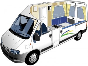
Fiat Ducato, Citroën Jumper, Renault Boxer 1994-2002 Workshop Repair & Service Manual in GERMAN

Fiat Ducato, Citroën Jumper, Renault Boxer 1994-2002 Workshop Repair & Service Manual in GERMAN (COMPLETE & INFORMATIVE for DIY REPAIR) ☆ ☆ ☆ ☆ ☆


INSTANT DOWNLOAD


* COMPLETE, Absolutely No Missing Pages!
* Customer Satisfaction GUARANTEED!

This high QUALITY official manual for Fiat Ducato, Citroën Jumper, Renault Boxer 1994-2002 is 100 percents COMPLETE and INTACT, no MISSING, CORRUPT pages, sections to freak you out! This manual is exactly as described. It is in the cross-platform PDF document format so that it works like a charm on all kinds of devices.

FORMAT: PDF
LANGUAGE: German
OS: Windows/Mac/Linux

Fiat Ducato, Citroën Jumper, Renault Boxer 1994 1995 1996 1997 1998 1999 2000 2001 2002

INSTANT DELIVERY: A download link will be sent to you instantly after payment. Simply click on the link and save it to your computer. You can use this Manual as long as you wish with no restrictions.

CUSTOMER SATISFACTION: If there is ANY kind of problem with the item you purchased, just drop a quick email. Within HOURS the issue shall be taken care of.

PRINTABLE MANUAL WITH DIAGRAMS: Just print the manual out and start to work. You can also use the manual with your Tablet/Laptop in your garage.

REFUND/EXCHANGE POLICY: We sell high QUALITY products only. However if you encounter any problems with the item you purchased, another replacement link will be sent to you. If we’re at fault, you will get 100 percents refund.

Buy ☆THE BEST MANUAL ON THE INTERNET☆ from responsible seller and get instant download now without uncertainty or surprise.

This highly detailed workshop service repair manual for download contains virtually everything you will ever need to repair, maintain, rebuild, refurbish or restore Your Fiat Ducato, Citroën Jumper, Renault Boxer 1994-2002 (ALL MODELS ARE COVERED). All diagnostic and repair procedures and gives you access to the same information that professional technicians and mechanics have. You can view and print out the complete repair procedures with this workshop service repair manual Download – you do not need to be skilled with a computer.

EXCERPTS:
Bei der folgenden Beschreibung beziehen wir uns auf die Benutzung eines Scherenwagenhebers und eines Rollwagenhebers sowie auf das Untersetzen von Böcken.
• Um ein Vorderrad mit einem Scherenwagenheber anzuheben, setzt man diesen an der in Bild 13 gezeigten Stelle unter das Fahrzeug.
• Um ein Vorderrad mit einem Rollwagenheber, wie in Bild 14 gezeigt, anzuheben, wird die gleiche Ansatzstelle wie beim Scherenwagenheber benutzt, mit dem Unterschied, dass man einen Holzklotz zwischen Wagenheberkopf und der Ansatzstelle einlegen sollte, wie man es in Bild 15 sehen kann.
• Unterstellböcke werden an der Vorderseite unter die gleichen Stellen wie der Wagenheber untergesetzt. Um dies erfolgreich zu bewerkstelligen, muss man den Wagenheber unter der inneren Traverse untersetzen, um genügend Raum zum Unterstellen des Bocks zu haben. Ein richtig untergestellter Bock sitzt an der in Bild 16 gezeigten Stelle. Die zum Absichern
benutzten Böcke sollten eine flache Auflagefläche haben.
Falls man nur Böcke mit „V”-Auflage hat, muss man den Raum entsprechend füllen. Wichtig ist, dass die Außenkante der Böcke nicht abrutschen können. Die folgenden Anweisungen gelten zum Anheben der Rückseite des Fahrzeuges:
• Einen Scherenwagenheber entsprechend Bild 17 benutzen. Diese Ansatzstelle liegt vor der Befestigung der Hinterfeder.
• Einen Rollwagenheber entsprechend Bild 18 ansetzen. Dies ist die gleiche Stelle wie für den Scherenwagenheber. Einen Holzklotz zwischen Wagenheberkopf und Ansatzstelle einsetzen, um keine Schäden anzurichten.
• Unterstellböcke werden unter die gleichen Stellen wie der Wagenheber angesetzt. Falls man das Fahrzeug zwecks Absicherung mit Unterstellböcken anheben will, hebt man das Fahrzeug an der Verbindung zwischen der Hinterfeder und der Traverse an, um die Unterstellböcke an der in Bild 19 gezeigten Stelle anzusetzen. Wie bereits oben erwähnt, sollten die Unterstellböcke eine flache Auflage haben.
• Beim Unterstellen von Böcken ist zu beachten, dass zur Reparatur von Personenwagen benutzte
Böcke hier nicht ausreichen. Die Höhe der Böcke wird durch Versetzen der Bolzen in den verschiedenen Löchern eingestellt. Bei Herstellung wird die Festigkeit der Bolzen der Tragkraft der Böcke angepasst.
Erfahrungen haben jedoch gezeigt, dass die mit den Bolzen verbundenen Ketten manchmal reißen und die Bolzen verloren gehen. Auf keinen Fall irgendwelche Schrauben geeigneten Durchmessers anstelle der Bolzen verwenden, es sei denn, dass diese aus Stahl hergestellt sind und die notwendige Tragkraft haben.
Hinweis: Aufgrund des Schwerpunktes des Fahrzeuges sollte man niemals zuerst eine Seite anheben und danach die andere, sondern zuerst vorn (oder hinten) und danach am anderen Ende. Dabei aufpassen, dass die gegenüberliegende Seite nicht abrutschen kann.
INSTANT DOWNLOAD


Posted on

Fiat Ducato 1999-2006 Workshop Repair & Service Manual (COMPLETE & INFORMATIVE for DIY REPAIR) ☆ ☆ ☆ ☆ ☆

Fiat Ducato 1999-2006 Workshop Repair & Service Manual (COMPLETE & INFORMATIVE for DIY REPAIR)

MFIATDCT9906NMMK
Price: $14.99 USD

Fiat Ducato 1999-2006 Workshop Repair & Service Manual (COMPLETE & INFORMATIVE for DIY REPAIR) ☆ ☆ ☆ ☆ ☆

* COMPLETE, Absolutely No Missing Pages!
* Official Service INFORMATION You Can Count On!
* Customer Satisfaction GUARANTEED!

MAKE: FIAT
MODEL: Ducato (aka Citroën Jumper_Relay, Peugeot Boxer, Ram Promaster) (2.0 16V, 2.0 JTD 8V, 2.3 JTD 16V, 2.8 JTD 8V)
YEAR: 1999 2000 2001 2002 2003 2004 2005 2006
LANGUAGE: EN/DE/ES/FR/IT/NL/PL/GK/PT/CZ/TR/RU
O.S.: Windows
FORMAT: CD ISO image
SIZE: 606 MB

This high QUALITY official manual for Fiat Ducato 1999-2006 is 100 percents COMPLETE and INTACT, no MISSING, CORRUPT pages, sections to freak you out! This manual is exactly as described.

INSTANT DELIVERY: A download link will be sent to you instantly after payment. Simply click on the link and save it to your computer. You can use this Manual as long as you wish with no restrictions.

CUSTOMER SATISFACTION: If there is ANY kind of problem with the item you purchased, just drop a quick email. Within HOURS the issue shall be taken care of.

PRINTABLE MANUAL WITH DIAGRAMS: Just print the manual out and start to work. You can also use the manual with your Tablet/Laptop in your garage.

REFUND/EXCHANGE POLICY: We sell high QUALITY products only. However if you encounter any problems with the item you purchased, another replacement link will be sent to you. If we’re at fault, you will get 100 percents refund.

Buy ☆THE BEST MANUAL ON THE INTERNET☆ from responsible seller and get instant download now without uncertainty or surprise.

This highly detailed workshop service repair manual for download contains virtually everything you will ever need to repair, maintain, rebuild, refurbish or restore Your Fiat Ducato 1999-2006 (ALL MODELS ARE COVERED). All diagnostic and repair procedures and gives you access to the same information that professional technicians and mechanics have. You can view and print out the complete repair procedures with this workshop service repair manual Download – you do not need to be skilled with a computer.

EXCERPTS:
DUCATO 2.0 16V CLUTCH WITH HYDRAULIC RELEASE DEVICE
COMPOSITION
A hydraulic release device has been fitted to improve acoustic comfort and performance while driving. This device consists of a reservoir shared with the brake system (1), pump (2) secured to the pedal unt, slave cylinder (3) secured to the gearbox bell housing and hydraulic damper (4).
The vehicle drives more comfortably because the damping effect of the hydraulic system reduces vibrations transmitted by the power unit.
The adoption of this device eliminates the need for periodic adjustment because clearance is eliminated and any wear on the driven plate is taken up automatically.
OPERATION
The clutch is single dry plate type, with a hydraulic release device and thrust bearing in permanent contact with the pressure spring. The driven plate is driven by pressure exercised by a diaphragm spring.
The clutch is released by a pedal-operated pump that transmits the fluid pressure increase to the slave cylinder piston. The piston acts on the clutch control fork via a rod to move the thrust bearing and thus overcome the action of the diaphragm spring.
The thrust bearing is in constant contact with the diaphragm spring and the slave cylinder rod is in constant contact with the fork.
Technical Data:
Spring load: 470 daN
Outer diameter: 224 mm
Inner diameter: 163 mm
Pedal stroke: 148.5 mm

SEATS
Specifications
– The seats are of vital importance in terms of comfort and safety: they are, in effect, the element that has to absorb the kinetic energy acquired by the body through the effect of stresses when cornering and during acceleration/deceleration. The structure of the seats has been designed to assist and complete the protection offered by the occupant protection system. The front seats have a robust frame under the cushion which has the task of maintaining correct support for the occupant in the case of a frontal impact and of minimizing the distortion of the seat.
– The cushion support frame and the special shape of the cushion base prevents the passengers from sliding under the seat belt lap strap in the case of strong deceleration known as the so-called anti-submarining effect.
Composition
– The exploded view of the driver’s seat is illustrated in the diagram
Front seats
– In the front part of the seating area there is an excellent structure for anti-submarining, to prevent the body sliding forward under the seat belt in the case of severe frontal impacts.
– This also contributes to limiting injury to the abdomen and femur by reducing the body’s forward acceleration.
– To assist back support the driver’s seat only has a modern support system (6) for the lumbar region specially designed and extended to wrap around the back and support it. A special knob (8) on the backrest is used for adjustments.
– The driver’s seat cushion can be height adjusted using two control levers; using knob (15) it is possible to adjust the height of the front part of the seat whilst knob (13) allows the height adjustment of the rear section.
– The angle of the backrest is adjusted using a rotary knob (9).
Heated front seats
– The heated seat (where fitted) is equipped with a heater pad located between the seat upholstery and the cover; this heater pad heats the cushion and the backrest at the same time. – The heating of the seat is activated by means of a special control located on the actual seat casing.


MFIATDCT9906NMMK
Price: $14.99 USD

Posted on

1995 Coupé Fiat, Coupé Fiat Turbo Workshop Repair & Service Manual (COMPLETE & INFORMATIVE for DIY REPAIR) ☆ ☆ ☆ ☆ ☆

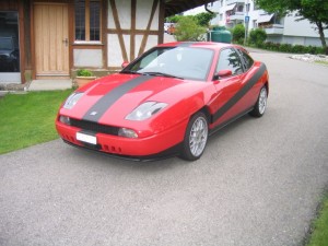
1995 Coupé Fiat, Coupé Fiat Turbo Workshop Repair & Service Manual (COMPLETE & INFORMATIVE for DIY REPAIR) ☆ ☆ ☆ ☆ ☆

MFIATC95OPEK.PDF
Price: $12.99 USD

1995 Coupé Fiat, Coupé Fiat Turbo Workshop Repair & Service Manual (COMPLETE & INFORMATIVE for DIY REPAIR) ☆ ☆ ☆ ☆ ☆

* COMPLETE, Absolutely No Missing Pages!
* Official Service INFORMATION You Can Count On!
* Customer Satisfaction GUARANTEED!

This high QUALITY official manual for 1995 Coupé Fiat, Coupé Fiat Turbo is 100 percents COMPLETE and INTACT, no MISSING, CORRUPT pages, sections to freak you out! This manual is exactly as described. It is in the cross-platform PDF document format so that it works like a charm on all kinds of devices.

FORMAT: PDF
LANGUAGE: English
OS: Windows/Mac/Linux

1995 Coupé Fiat, Coupé Fiat Turbo (Type 175), 861 Pages

INSTANT DELIVERY: A download link will be sent to you instantly after payment. Simply click on the link and save it to your computer. You can use this Manual as long as you wish with no restrictions.

CUSTOMER SATISFACTION: If there is ANY kind of problem with the item you purchased, just drop a quick email. Within HOURS the issue shall be taken care of.

PRINTABLE MANUAL WITH DIAGRAMS: Just print the manual out and start to work. You can also use the manual with your Tablet/Laptop in your garage.

REFUND/EXCHANGE POLICY: We sell high QUALITY products only. However if you encounter any problems with the item you purchased, another replacement link will be sent to you. If we’re at fault, you will get 100 percents refund.

Buy ☆THE BEST MANUAL ON THE INTERNET☆ from responsible seller and get instant download now without uncertainty or surprise.

This highly detailed workshop service repair manual for download contains virtually everything you will ever need to repair, maintain, rebuild, refurbish or restore Your 1995 Coupé Fiat, Coupé Fiat Turbo (ALL MODELS ARE COVERED). All diagnostic and repair procedures and gives you access to the same information that professional technicians and mechanics have. You can view and print out the complete repair procedures with this workshop service repair manual Download – you do not need to be skilled with a computer.

EXCERPTS:
FUEL EVAPORATION CONTROL ANO VAPOR RECOVERY CIRCUIT
When engine operates in non turbocharged range, the fuel evaporation control circuit adopted on the turbo version is similar to that used on the aspirated version with pneumatic cut-off valve (4) regulated by pressure inside the intake duct.
During turbocharged operation, system operation is ensured by the presence of a second cut-off valve (SIEMENS) (1). This valve is also controlled by the pressure inside the engine supply duct, however it only opens when the duct pressure exceeds atmospheric pressure (turbocharging).
During turbocharging, the system operates as follows:
• fuel vapor cut-off valve (4) is closed by turbocharging pressure in duct upstream of throttle valve;
• at the same time, the SIEMENS valve (1). opened as a result of pressure in supply duct, brings the active carbon trap filter (3). via a 3-way connection (6), into communication with compressor inlet (2)
which sucks in the fuel vapor.
The circuit is also fined with a vapor/liquid separator that allows some of the fuel vapors to condense
and flow back to the tank 1n a liquid state.

REMOVING-REFITTING POWER UNIT
1. Drain the air conditioning system by connecting the red hose, of the special equipment, to the needle valve (1) and the blue hose to the needle valve (2); then proceed as described in Section 50 of this manual.
Before carrying out any operation that could cause the emergence of the R134 A coolant, drain the air conditioning system. Wear protective gloves and goggles while draining the system, in order to protect against harmful contact of splashes of R 134A. To facilitate the emptying of the coolant from the air conditioning system, the system should be operated with the engine running for about 10-15 minutes.
Place the car on ramps, disconnect the battery’s negative pole, remove the front wheels, then proceed as described below:
2. Disconnect the air inlet duct, complete with resonator, by undoing the bolts shown in the figure which attach it to its mounting brackets.
3. Remove the cover on the i.e. cable/front cable connections from the engine compartment.
4. Lift the protective cover from the positive pole, then disconnect the cable; undo the nut securing the battery to the cage and take the battery out of the engine compartment.


MFIATC95OPEK.PDF
Price: $12.99 USD

Posted on

1991-1998 Cinquecento Workshop Repair & Service Manual in Italian (COMPLETE & INFORMATIVE for DIY REPAIR) ☆ ☆ ☆ ☆ ☆

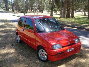
1991-1998 FIAT Cinquecento Workshop Repair & Service Manual in Italian (COMPLETE & INFORMATIVE for DIY REPAIR)

MFIATCQCT9198OPIK.PDF
Price: $14.99 USD

1991-1998 FIAT Cinquecento Workshop Repair & Service Manual in Italian (COMPLETE & INFORMATIVE for DIY REPAIR) ☆ ☆ ☆ ☆ ☆

* COMPLETE, Absolutely No Missing Pages!
* Official Service INFORMATION You Can Count On!
* Customer Satisfaction GUARANTEED!

This high QUALITY official manual for ’91-’98 Cinquecento is 100 percents COMPLETE and INTACT, no MISSING, CORRUPT pages, sections to freak you out! This manual is exactly as described. It is in the cross-platform PDF document format so that it works like a charm on all kinds of devices.

FORMAT: PDF
LANGUAGE: ITALIAN
SIZE/PAGE: 2,673 Pages
OS: Windows/Mac OS X/Linux/Android/iOS

INSTANT DELIVERY: A download link will be sent to you instantly after payment. Simply click on the link and save it to your computer. You can use this Manual as long as you wish with no restrictions.

CUSTOMER SATISFACTION: If there is ANY kind of problem with the item you purchased, just drop a quick email. Within HOURS the issue shall be taken care of.

PRINTABLE MANUAL WITH DIAGRAMS: Just print the manual out and start to work. You can also use the manual with your Tablet/Laptop in your garage.

REFUND/EXCHANGE POLICY: We sell high QUALITY products only. However if you encounter any problems with the item you purchased, another replacement link will be sent to you. If we’re at fault, you will get 100 percents refund.

Buy ☆THE BEST MANUAL ON THE INTERNET☆ from responsible seller and get instant download now without uncertainty or surprise.

This highly detailed workshop service repair manual for download contains virtually everything you will ever need to repair, maintain, rebuild, refurbish or restore 1991 1992 1993 1994 1995 1996 1997 1998 Cinquecento. All diagnostic and repair procedures and gives you access to the same information that professional technicians and mechanics have. You can view and print out the complete repair procedures with this workshop service repair manual Download – you do not need to be skilled with a computer.

EXCERPTS:
Impianto elettrico
Accensione elettronica nanoplex
ACCENSIONE ELETTRONICA AD ANTICIPO E DISTRIBUZIONE STATICA NANOPLEX
Generalità
Il sistema di accensione adottato su questo motore bicilindrico è denominato Nanoplex ed è un sistema di accensione elettronica ad anticipo e distribuzione statico (cioè non avente alcuna parte in movimento) a scintilla persa.
Il sistema è composto da un microprocessore che conosce lo stato di funzionamento del motore attraverso ad alcuni sensori periferici ed aziona la corrente di carica del rocchetto d’accensione per il tempo (valore della corrente di carica) ed al momento (angolo di anticipo accensione) più opportuni secondo le mappature memorizzate in due curve d’anticipo. L’angolo di anticipo adottato è in funzione del numero dei giri e del carico motore istantanei.
Questo sistema è costituito dai seguenti particolari.
a) Un sensore elettromagnetico (2) affacciato alla puleggia albero motore che fornisce al modulo elettronico di comando accensione le informazioni di numero di giri motore nell’unità di tempo e posizione di P.M.S. degli stantuffi.
b) Una puleggia albero motore (3) specifica sulla cui circonferenza sono ricavati tre risalti (o denti) che servono al sensore per produrre dei segnali di numero di giri e P.M.S. stantuffi.
c) Un modulo elettronico, o centralina, (1) comando accensione che in funzione dei valori istantanei del numero di giri, della posizione di P.M.S. e del funzionamento del motore (a pieno carico oppure a carichi parziali) piloti per il tempo opportuno la corrente di conduzione del primario (da 7, 1 A al minimo a 3,5 A a 5900/min) e la interrompa istantaneamente; inoltre, in fase di avviamento, garantisca il funzionamento del motore anche con tensioni della batteria di 6V, mentre a 1000/min lo deve garantire con tensioni tra 6 e 1 O V.; infine tagli l’alimentazione al primario a 6000/min e la riattivi a 5900/min. e mantenga negli angoli d’anticipo d’accensione delle tolleranze di ± 2° da 450 /min al massimo regime, di – 2° da 200/min-;- 400/min ed infine, in fase di avviamento, un ritardo massimo di – 8° fino a 200/min.
d) Un interruttore a depressione, o manocontatto, (4) che serve da ingresso aperto-chiuso (ON-OFF) di segnale logico delle condizioni di pieno carico o carico parziale del motore affinché il microprocessore di comando del sistema accensione adotti, delle due curve disponibili, quella più appropriata alle condizioni di funzionamento del motore.
e) Un rocchetto di accensione (5) con doppio terminale ad alta tensione costituito da un avvolgimento primario a bassa induttanza (alimentato dalla tensione di batteria) e da un avvolgimento se- .1 conciario (alta tensione) le cui due uscite sono direttamente collegate alle candele cui provvedono a mandare l’alta tensione ogni qualvolta avviene la smagnetizzazione del primario da parte del modulo elettronico di comando.
L’alta tensione che alimenta contemporaneamente le due candele, data la caratteristica di chiusura del circuito secondario (candela posta in serie) sarà di intensità diversa. Ciò è dovuto al fatto che periodicamente una delle due candele si troverà in condizioni di maggior pressione (fase di compressione) nei confronti dell’altra (fase di scarico) cosicché la corrente, dovendo vincere un maggior dielettrico nella candela che si troverà in fase di compressione, darà origine ad una scintilla più potente in questa, mentre nell’altra sarà irrisoria (limitandone il consumo).
L’accensione Nanoplex dispone di una funzione diagnosi su una linea bidirezionale che esegue in “input” la diagnosi attiva ed in “output” l’autodiagnosi, cosicché con il Fiat-Lancia tester è possibile colloquiare con il sistema d’accensione per ottenere i’AUTODiAGNOSi del sistema.
E una induttanza variabile – composta da una calamita e da un avvolgimento – che si rafforza quando un risalto della puleggia albero motore s’affaccia alla calamita e si indebolisce ed inverte quando il risalto s’allontana. Durante il funzionamento del motore si sviluppa nel sensore una f.e.m. alternata (la cui frequenza viene utilizzata per leggere i giri motore) con una irregolarità di frequenza (che serve ad individuare il PMS).


MFIATCQCT9198OPIK.PDF
Price: $14.99 USD

Posted on

Fiat Bravo, Brava 1995-2001 Workshop Repair & Service Manual (COMPLETE & INFORMATIVE for DIY REPAIR) ☆ ☆ ☆ ☆ ☆

Fiat Bravo, Brava 1995-2001 Workshop Repair & Service Manual (COMPLETE & INFORMATIVE for DIY REPAIR) ☆ ☆ ☆ ☆ ☆

MFIATBRV9501OPMS.PDF
Price: $14.99 USD

Fiat Bravo, Brava 1995-2001 Workshop Repair & Service Manual (COMPLETE & INFORMATIVE for DIY REPAIR) ☆ ☆ ☆ ☆ ☆

* COMPLETE, Absolutely No Missing Pages!
* Official Service INFORMATION You Can Count On!
* Customer Satisfaction GUARANTEED!

This high QUALITY official manual for Fiat Bravo, Brava 1995-2001 is 100 percents COMPLETE and INTACT, no MISSING, CORRUPT pages, sections to freak you out! This manual is exactly as described. It is in the cross-platform PDF document format so that it works like a charm on all kinds of devices.

MAKE: FIAT
MODEL: Bravo, Brava
YEAR: 1995 1996 1997 1998 1999 2000 2001
LANGUAGE: EN/IT
FORMAT: PDF
SIZE/PAGE: 383 MB (10,000+ Pages)

INSTANT DELIVERY: A download link will be sent to you instantly after payment. Simply click on the link and save it to your computer. You can use this Manual as long as you wish with no restrictions.

CUSTOMER SATISFACTION: If there is ANY kind of problem with the item you purchased, just drop a quick email. Within HOURS the issue shall be taken care of.

PRINTABLE MANUAL WITH DIAGRAMS: Just print the manual out and start to work. You can also use the manual with your Tablet/Laptop in your garage.

REFUND/EXCHANGE POLICY: We sell high QUALITY products only. However if you encounter any problems with the item you purchased, another replacement link will be sent to you. If we’re at fault, you will get 100 percents refund.

Buy ☆THE BEST MANUAL ON THE INTERNET☆ from responsible seller and get instant download now without uncertainty or surprise.

This highly detailed workshop service repair manual for download contains virtually everything you will ever need to repair, maintain, rebuild, refurbish or restore Fiat Bravo, Brava 1995-2001. All diagnostic and repair procedures and gives you access to the same information that professional technicians and mechanics have. You can view and print out the complete repair procedures with this workshop service repair manual Download – you do not need to be skilled with a computer.

EXCERPTS:
HITACHI INTEGRATED INJECTION/IGNITION SYSTEM
Introduction
The Hitachi system fitted on the Bravo-Brava with the 1747 i.e 16v engine belongs to the category of static advance digital electronic ignition systems integrated with multiple phased type intermittent electronic fuel injection systems.
This system therefore has only one control unit, one set of wiring and one set of common sensors for both systems.
The integrated system can be summarized in the following sub systems:
ELECTRICAL/ELECTRONIC CIRCUIT
AIR INTAKE CIRCUIT
FUEL SUPPLY CIRCUIT
EMISSION CONTROL DEVICES
The system is capable of detecting the following parameters via special sensors:
1 . the engine rotation speed;
2. the position of each pair of pistons in relation to TDC for cylinder 1;
3. the engine intake air flow rate;
4. the position and the speed of the variation of the position of the accelerator butterfly;
5. the temperature of the engine coolant;
6. the effective strength of the mixture (through the Lambda sensor signal);
7. the presence of detonation;
8. the speed of the vehicle;
9. the battery voltage;
10. whether the climate control compressor is switched on.
This information, usually of an analogue type, is converted into digital signals by analogue/digital (A/D) converters in order to be able to be used by the control unit.
In particular, any engine operating point is detected, moment by moment, by two parameters:
– the engine rotation speed, measured in revolutions per minute (rpm);
– the engine load, which is constituted by the quantity of air drawn in by each cylinder.
This quantity is calculated on the basis of the flow rate of the air drawn in and is represented by the parameter TP, measured in milliseconds (ms).
Inside the control unit memory there is a management program (software) which comprises a series of strategies, each of which manages a precise system control function.
By using the (input) information listed previously, each strategy processes a series of parameters, based on the data maps stored in the control unit memories and then controls the system (output) actuators which are the devices which allow the engine to operate, namely:
1. injectors;
2. ignition coils;
3. solenoid valves implementing various functions;
4. fuel pump;
5. control relays.
NOTE The HITACHI injection/ignition system does not require any adjustment as it is self-regulating and self-adjusting.
NOTE In the diagrams, the numbers indicate the corresponding HITACHI engine control unit pins.
NOTE All the connectors are seen from the side opposite the cable input.


MFIATBRV9501OPMS.PDF
Price: $14.99 USD