Posted on

Case/Steyr 9000-Series Tractors Factory Service & Shop Manual


Download Link

INSTANT DOWNLOAD (add to cart)


Case/Steyr 9000-Series Tractors Factory Service & Shop Manual
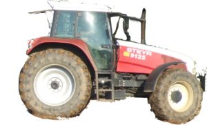

total 3,086 pages, bookmarked, Searchable, Printable, high quality PDF

“7-96100”
Case Steyr M9078, M9086, M9094 Tractors Service – Training Manual
SVA 7-96101; 161 MB PDF
CASE / CNH / STEYR: 9105, 9115, 9125, 9145, CS68, CS75, CS78, CS78a, CS86, CS86a, CS94, CS94a, CS100, CS110, CS120, CS130, CS150, M968, M975, M9078, M9078a, M9086, M9086a, M9094, M9094a, WD320, WD420

“7-96211”
CNH Österreich 9105, 9115, 9125, 9145 Tractors Service – Training Manual
SVA 7-96212; 233 MB PDF
CASE / CNH / STEYR: 9105, 9105a, 9115, 9115a, 9125, 9125a, 9145, 9145a, CS68, CS75, CS78, CS86, CS94, CS100, CS110, CS120, CS130, CS150

Complete workshop & service manual with electrical wiring diagrams for CNH/Case Steyr olde 9000 Series Tractors. It’s the same service manual used by dealers that guaranteed to be fully functional and intact without any missing page.

This CNH/Case Steyr 9000-Series Tractors (9105, 9105a, 9115, 9115a, 9125, 9125a, 9145, 9145a, CS68, CS75, CS78, CS78a, CS86, CS86a, CS94, CS94a, CS100, CS110, CS120, CS130, CS150, M968, M975, M9078, M9078a, M9086, M9086a, M9094, M9094a, WD320, WD420) service & repair manual (including maintenance, overhaul, disassembling & assembling, adjustment, tune-up, operation, inspecting, diagnostic & troubleshooting…) is divided into different sections. Each section covers a specific component or system with detailed illustrations. A table of contents is placed at the beginning of each section. Pages are easily found by category, and each page is expandable for great detail. The printer-ready PDF documents work like a charm on all kinds of devices.

EXCERPT:
2. FLYWHEEL CASING
A. Fitting the flywheel casing
The flywheel casing is centered on the cylinder block by means of two sprung dowel pins. The flywheel casings, which are also available as a spare part, are supplied with the bore holes for the pins.
1. Clean the sealing surfaces between the cylinder block and flywheel housing.
2. Apply sealant (e.g. silicone) to the points shown in the figure.
3. Lift the flywheel casing to the correct position and insert all the bolts.
4. Centre the casing and fit the sprung dowel pins using a mandrel.
5. Tighten the inner ring bolts to a torque of 60 Nm and the outer ring bolts to a torque of 110 Nm.
B. Replacing the rear crankshaft sealing ring
1. Separate the tractor between the engine and power unit.
2. Remove the flywheel.
3. Remove the sealing ring without damaging the crankshaft.
4. Clean the sealing ring seat and grind any burr.
NOTE: If the crankshaft is worn at the sealing ring seat, a 2 mm spacer ring (spare part number 162000020718 can be fitted behind the crankshaft sealing ring.
5. Carefully press the sealing ring in down to the bottom of the flywheel casing using the 1TSW 521 and 1TSW 662 fitting tools.
NOTE: THE ASSEMBLY PROCEDURE MUST BE CARRIED OUT IN A DRY AND OIL-FREE STATE.

Posted on

Case 1850K Crawler Dozer Factory Service & Shop Manual


Download Link

INSTANT DOWNLOAD (add to cart)


1,000+ total pages, bookmarked, Searchable, Printable, high quality PDF

“6-46480.pdf”
CASE 1850K CRAWLER DOZER Service Manual
290 pages

“9-54241.pdf”
CASE 1850K (Tier 2) CRAWLER DOZER Workshop Manual
384 pages

“87630287.pdf”
CASE 1850K (Tier 3) CRAWLER DOZER Repair Manual
465 pages

Complete workshop service manual with electrical wiring diagrams for Case 1850K Crawler Dozer. It’s the same service manual used by dealers that guaranteed to be fully functional and intact without any missing page.

This 1850K service & repair manual (including maintenance, overhaul, disassembling & assembling, adjustment, tune-up, operation, inspecting, diagnostic & troubleshooting…) is divided into different sections. Each section covers a specific component or system with detailed illustrations. A table of contents is placed at the beginning of each section. Pages are easily found by category, and each page is expandable for great detail. The printer-ready PDF documents work like a charm on all kinds of devices.

EXCERPT:

FINAL DRIVES
3.1 GENERAL DESCRIPTION
The final drives are of a double reduction type, with straight spur gears and a 1 : 12.286 reduction ratio.
Specifications of final drive oil: must meet MIL-2105 or AKCELA Gear 135 HEP (SAE 80W-90).
Quantity to fill with oil final drives: 33 litres (8.7 gal.).
The 1850K final drives have two features, one of a technical type, the other service oriented.
The technical feature consists of a different arrangement of the final drives, being isolated from the stress generated by the undercarriage, which, on the other hand, is directly connected to the transmission housing, absorbing the majority of the loads on the track
chains through the hinging on the two shafts (PIVOT – SHAFTS).
The service feature consists of the reduction of the service time required to intervene on the machine,
since the modular type final drives are individually removable from the unit, without involving the transmission housing.
Final drive installed

Posted on

Case 1845 Uni-Loader Factory Service & Shop Manual


Download Link

INSTANT DOWNLOAD (add to cart)


Case 1845 Uni-Loader Factory Service & Shop Manual

666 pages, bookmarked, Searchable, Printable, high quality PDF
9-73926 – 1845 Uni-Loader Service Manual.pdf

Complete workshop & service manual with electrical wiring diagrams for Case 1845 Uni-Loader. It’s the same service manual used by dealers that guaranteed to be fully functional and intact without any missing page.

This Case 1845 Uni-Loader service & repair manual (including maintenance, overhaul, disassembling & assembling, adjustment, tune-up, operation, inspecting, diagnostic & troubleshooting…) is divided into different sections. Each section covers a specific component or system with detailed illustrations. A table of contents is placed at the beginning of each section. Pages are easily found by category, and each page is expandable for great detail. The printer-ready PDF documents work like a charm on all kinds of devices.

EXCERPT:
ENGINE REMOVAL
1. Drain cooling system.
2. Remove radiator and oil cooler assembly as instructed in Section 2054.
3. On diesel engine, disconnect or remove from the left side of the engine:
a. Battery and engine ground cables from starter mounting bolt. Tape end of battery ground cable to prevent accidental grounding.
b. Battery cable and wiring from starter solenoid.
c. Wire from engine temperature sender.
d. Wiring from alternator. Then make sure wiring harness is free of engine and place out of way.
e. Hose between air cleaner and intake manifold.
4. On diesel engine, disconnect or remove from right hand side of engine:
a. Throttle rod and fuel shutoff cable at the injection pump. Remove throttle rod from cross-shaft, and shutoff cable clamp from engine block and place cable out of way.
b. Fuel supply line at fuel filter and return line from the No. 4 injector.
Plug hoses to prevent fuel tank from draining.
c. Wire from engine oil pressure sender.
5. On gas engine, disconnect or remove from left side of engine:
a. Fuel line at fuel pump. Remove hose and clamp and plug hose to prevent fuel tank from draining.
b. Battery and engine ground cables from starter mounting bolt. Tape end of battery ground to prevent accidental grounding.
c. Battery cable and wiring from starter solenoid.
d. Throttle rod at linkage on engine block.
e. Wiring from engine temperature sender, ignition coil and alternator.
Make sure wiring harness is free of engine and place out of way.
6. On gas engine, disconnect or remove from right hand side of engine:
a. Choke cable at carburetor. Remove cable from clamp and place cable out of way.
b. Wire from engine oil pressure sender.
c. Hose between carburetor and air cleaner.
7. Remove muffler and hydraulic system oil filter housing.
8. Remove the flywheel guard and remove the drive coupling to flywheel cap screws and flat washers.
9. Remove cotter pins from the front and rear engine mounting bolts and remove nuts, flat washers and bolts.
10. Attach lifting sling to engine and lifting device to sling.
11. Carefully remove engine from rear of machine.

Posted on

Case 1835B Uni-Loader Workshop Repair & Service Manual


Download Link

INSTANT DOWNLOAD (add to cart)


Case 1835B Uni-Loader Workshop Repair & Service Manual

1,038 pages, bookmarked, Searchable, Printable, high quality PDF
Case 1835B Uni-Loader Service Manual.pdf; 1,038 pages

Complete digital official shop manual contains service, maintenance, and troubleshooting information for the Case 1835B Uni-Loader. Diagnostic and repair procedures are covered in great detail to repair, maintain, rebuild, refurbish or restore your Case 1835B Uni-Loader like a professional mechanic in local service/repair workshop. This cost-effective quality manual is 100% complete and intact as should be without any missing pages. It is the same factory shop manual used by dealers that guaranteed to be fully functional to save your precious time.

This manual for Case 1835B Uni-Loader is divided into different sections. Each section covers a specific component or system and, in addition to the standard service procedures, includes disassembling, inspecting, and assembling instructions. A table of contents is placed at the beginning of each section. Pages are easily found by category, and each page is expandable for great detail. It is in the cross-platform PDF document format so that it works like a charm on all kinds of devices. You do not need to be skilled with a computer to use the manual.

EXCERPT:
18358 UNI-LOADER
TABLE OF CONTENTS
Safety Rules, Service Manual Introduction, and Torque Specifications .. 1001
Maintenance and Lubrication .. 1082
General Engine Specifications -188 Diesel Engine .. 1010
Detailed Engine Specifications -188 Diesel Engine … 1027
General Engine Specifications- 148 Spark Ignition Engine .. 1110
Detailed Engine Specifications- 148 Spark Ignition Engine .. 1129
2 ENGINES
Engine Removal and Installation, Engine Accessories (Air Cleaner, Muffler, Ether Injection System, Radiator) .. 2000
188 DIESEL ENGINE
Engine Diagnosis .. 2001
Engine Tune-Up … 2002
Cylinder Head, Valve Train, and Camshaft … 2015
Cylinder Block, Sleeves, Pistons, and Rods … 2025
Crankshaft, Bearings, Flywheel, and Oil Seals .. 2035
Oil Pump .. 2045
Cooling System … 2055
Engine Lubrication .. See Section 2555
148 SPARK IGNITION ENGINE
Engine Tune-Up … 2102
Cylinder Head, Valve Train, and Camshaft … 2115
Cylinder Block, Sleeves, Pistons, and Rods … 2125
Crankshaft, Bearings, Flywheel, and Oil Seals .. 2135
Oil Pump … 2145
Cooling System … … 2155
Engine Lubrication- 188 Diesel Engine .. 2555
3 FUEL SYSTEM
Engine Controls, Fuel Line, Fuel Tank, and Hand Pr!mer Pump. 3001
Fuel Filters- 188 Diesel Engine … 301G
Fuel Injection Pump- 188 Diesel Engine … 3012
Fuel Injectors- 188 Diesel Engine .. 301’3
Carburetor- 148 Spark Ignition Engine .. 311’2′
4 ELECTRICAL
Electrical System Troubleshooting … 4002
Wiring Diagrams … 4003
Fuel Gauge and Warning Lamps .. 4004
Battery .. 4005
Starter … 4006·
Alternator .. 4007
Distributor Ignition System … 4008
6 POWER TRAIN
Hydrostatic System Troubleshooting . 6002
Hydrostatic System Diagrams and Operation … 6003
Piston Pump .. 6004
Hydrostatic Motor … 6005″
Hydrostatic Controls .. 6006
Drive Sprockets, Chains, and Axle Housings … 6007
Drive Coupling .. 6010
Wheels and Tires .. 6011
7 BRAKES
Parking Latch … 7001
8 HYDRAULICS
Hydraulic System Specifications, Diagrams, Troubleshooting,
Pressure Checks, Flowmeter Tests . 8002
Cleaning the Hydraulic System … 8003
Equipment and Charge Pump .. 8004
Loader Control Valve .. 8005
Auxiliary Control Valve .. 8006
Backhoe Control Valve .. 8007
Cylinders .. 8009
9 MOUNTED EQUIPMENT
Loader … 9001
Backhoe … 9002
ROPS Canopy, Operators Seat … 9003
Decals, Painting, and Noise Control .. 9005

Crankshaft Inspection And Installation
STEP 115
Measure the main bearing journals to see if the journals are worn. Measure the front and rear of each journal. Use undersize bearing liners if the diameters are smaller than 2.6230″ (66.6242 mm). 0.002″ (0.0508 mm) undersize bearing liners can be used without grinding the journals to keep the specified bearing clearance.
NOTE: Grind the crankshaft journals undersize 0.010″ (0.254 mm), 0.020″ (0.508 mm) or 0.040″ (1.016 mm) if the crankshaft journals are worn more than 0.002″ (0.0508 mm). See Section 1129 of the Service Manual for the grinding dimensions.
STEP 116
Measure the main bearing journals, again, 90 degrees from the first measurements (Step 115) for out-of-round. Grind the journals and use undersize liners if the out-of-round is more than 0.0005″ (0.0127 mm).
STEP 117
Measure the connecting rod journals for taper.
Measure the front and rear of each journal. Grind the journals if the taper is more than 0.002″ (0.0508 mm).
STEP 118
Check the rod journals again, 90 degrees from the first measurements (Step 117) for out-of-round.
Grind the journals if the out-of-round is more than 0.001″ (0.0254 mm).
STEP 119
Remove the crankshaft gear if the gear is damaged or worn. Use a puller to remove the gear.
STEP 120
Heat the crankshaft gear. Use a bearing heater oven (CAS-10133).
STEP 121
Install the key and the heated crankshaft gear on the crankshaft.
A CAUTION Always wear asbestos gloves to prevent burning your hands when handling heated parts.
STEP 122
Make sure that the timing mark on the gear is on the outside.
STEP 123
Make sure that the bearing liner bores are clean.
Install the main bearing liners.
NOTE: Make sure that the liner locks are aligned when installing the liners. Slide the liners in position.
Never push on the center of the liners.
Lubricate the bearing liners. Use clean engine oil.

Posted on

Case 1650K Crawler Dozer Factory Service & Shop Manual


Download Link

INSTANT DOWNLOAD (add to cart)


Case 1650K Crawler Dozer Factory Service & Shop Manual

243 pages, bookmarked, Searchable, Printable, high quality PDF
9-54970 English – Case 1650K (Tier 2) Crawler Dozer Workshop Manual.pdf

Complete workshop & service manual with electrical wiring diagrams for Case 1650K Crawler Dozer . It’s the same service manual used by dealers that guaranteed to be fully functional and intact without any missing page.

This Case 1650K Crawler Dozer service & repair manual (including maintenance, overhaul, disassembling & assembling, adjustment, tune-up, operation, inspecting, diagnostic & troubleshooting…) is divided into different sections. Each section covers a specific component or system with detailed illustrations. A table of contents is placed at the beginning of each section. Pages are easily found by category, and each page is expandable for great detail. The printer-ready PDF documents work like a charm on all kinds of devices.

EXCERPT:
SUMMARY
GENERALITIES
ENGINE
TRANSMISSION
FINAL DRIVES
BRAKES AND STEERING
UNDERCARRIAGE
DOZER EQUIPMENT
HYDRAULIC SYSTEM
ELECTRICAL SYSTEM

TRANSMISSION
Carefully read personal and machine SAFETY PRECAUTIONS (at the beginning of this manual)
2.1.1 TRANSMISSION TORQUE
CONVERTER HYDRAULIC DIAGRAM
The transmission is of a “power-shift” type with three forward and three reverse speeds. The system is powered by a dual pump feeding the transmission and the torque converter (1).
The pump sucks oil from the transmission housing through filter (6) and circulates it purifying further through filter (2). A valve (set at 2.5 bar) (36.25 psi)
protects filter (2) against over pressures due to the clogging of the cartridge or excessively thick oil.
The oil delivered by feeding pump (1) after being purified by filter (2) reaches pressure relief valve (3) establishing and maintaining the pressure setting of the oil controlling the transmission clutches.
Safety valve (16) protects the torque converter and the heat exchanger against accidental pressure increments, normally due to cold and excessively thick oil, discharging the flow excess into the pump delivery line (1).
2.1 GENERAL DESCRIPTION
The oil flowing out the torque converter, passes through the heat exchanger, the manifold and it is distributed to the lube and cooling ducts of the transmission clutches.
The maximum lube pressure is limited by valve (15) set at 3 bar (43.5 psi).
Modulating valves (9) make the engagement of the clutches progressive, regulating the pressure increment in the control circuits.
A low engine lube oil pressure or an excessive lube oil temperature are indicated on the dashboard in the cab.
Quick discharge valves on the 2nd and 3rd speed clutches, during the speed engagement phase, are in closed position, under the action of pressurised oil.
When shifting from one speed to another, the relevant control cylinder is connected to the discharge and the pressure drop causes the centrifugal force to prevail over the action of the oil, moving the balls outwards, facilitating a quick discharge.