Pages from 9813-0200 – JCB Telescopic Handler 527-58 Service Manual
Complete workshop & service manual with electrical wiring diagrams for JCB Telescopic Handler 527-58. It’s the same service manual used by dealers that guaranteed to be fully functional and intact without any missing page.
This JCB Telescopic Handler 527-58 service & repair manual (including maintenance, overhaul, disassembling & assembling, adjustment, tune-up, operation, inspecting, diagnostic & troubleshooting…) is divided into different sections. Each section covers a specific component or system with detailed illustrations. A table of contents is placed at the beginning of each section. Pages are easily found by category, and each page is expandable for great detail. The printer-ready PDF documents work like a charm on all kinds of devices.
9813-0200 – JCB Telescopic Handler 527-58 Service Manual.pdf
EXCERPT:
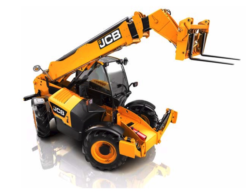
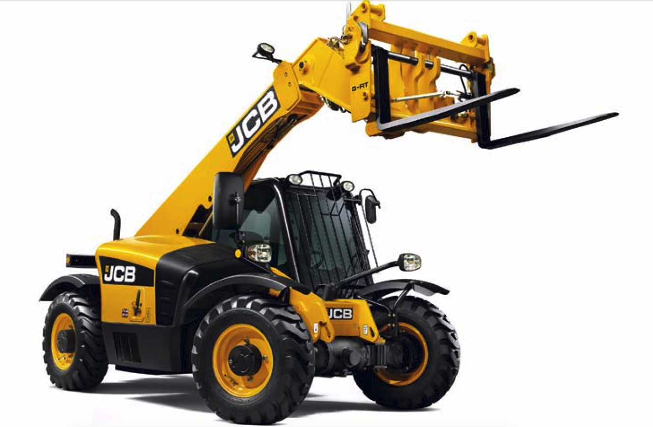
527-58
Section 1 – General Information
Section 2 – Care and Safety
Section 3 – Routine Maintenance
Section B – Body and Framework
Section C – Electrics
Section E – Hydraulics
Section F – Transmission
Section G – Brakes
Section H – Steering
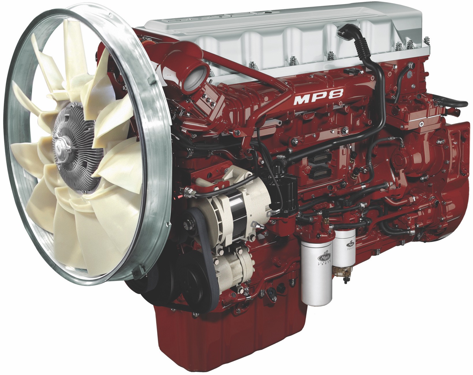
Section K – Engine
Section M – Electronic Data Systems
…
Left Hand Switch Panel
Removal
1 Park the machine and make it safe. Obey the care and safety procedures. Refer to Section 2 – General Procedures. K Related Topics ( T B5-3)
2 Remove the two screws A that hold the left hand switch panel B in place, disconnect all connections and remove the panel.
3 To remove the rotary switch E:
a Remove the knob C from the front of the panel D.
b Mark the position of the switch housing E in relation to the trim panel D.
c Unscrew the locknut F and remove the switch E from the panel D.
…