Posted on

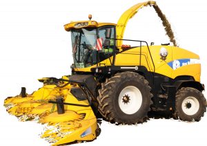
New Holland FR9040, FR9050, FR9060, FR9080, FR9090 Forage Harvester Factory Service & Shop Manual


Pages from 87725913D – FR9040, FR9050, FR9060, FR9080, FR9090 Service Manual


INSTANT DOWNLOAD


Complete workshop & service manual with electrical wiring diagrams for New Holland FR9040, FR9050, FR9060, FR9080, FR9090 Forage Harvester. It’s the same service manual used by dealers that guaranteed to be fully functional and intact without any missing page.

This New Holland FR9040, FR9050, FR9060, FR9080, FR9090 Forage Harvester service & repair manual (including maintenance, overhaul, disassembling & assembling, adjustment, tune-up, operation, inspecting, diagnostic & troubleshooting…) is divided into different sections. Each section covers a specific component or system with detailed illustrations. A table of contents is placed at the beginning of each section. Pages are easily found by category, and each page is expandable for great detail. The printer-ready PDF documents work like a charm on all kinds of devices.

87725913D – FR9040, FR9050, FR9060, FR9080, FR9090 Forage Harvester Service Manual – 2,953 pages

Link Product / Engine
Product Market Product Engine
FR9040 North America F2CE9684U*E151
FR9040 Latin America F2CE9684U*E151
FR9040 International
Region
F2CE9684U*E151
FR9040 Europe F2CE9684U*E151
FR9050 North America F3BE0684J*E811
FR9050 Europe F3BE0684J*E811
FR9050 International
Region
F3BE0684J*E811
FR9050 Latin America F3BE0684J*E811
FR9060 International
Region
F3CE0684A*E814
FR9060 Europe F3CE0684A*E814
FR9060 Latin America F3CE0684A*E814
FR9060 North America F3CE0684A*E814
FR9090 North America FVAE2884X*B200
FR9090 Europe FVAE2884X*B200
FR9090 International
Region
FVAE2884X*B200

EXCERPT:
Contents
INTRODUCTION
Engine………10
[10.001] Engine and crankcase. ……10.1
[10.218] Fuel injection system…….10.2
[10.400] Engine cooling system. ……10.3
[10.414] Fan and drive. …….10.4
[10.418] Rotary screen. …….10.5
Main gearbox and drive …….14
[14.100] Main gearbox and drive. ……14.1
Transmission………..21
[21.114] Mechanical transmission. ……21.1
[21.130] Mechanical transmission external controls…..21.2
[21.100] Mechanical transmission lubrication system. ….21.3
[21.145] Gearbox internal components……21.4
[21.182] Differential………21.5
Four-Wheel Drive (4WD) system …..23
[23.101] Mechanical control. …….23.1
[23.304] Four-Wheel Drive (4WD) gearbox. …..23.2
Front axle system ….25
[25.100] Powered front axle. …….25.1
[25.102] Front bevel gear set and differential. …..25.2
[25.310] Final drives. ……..25.3
Rear axle system…..27
[27.450] Rear-powered steerable axle. …..27.1
[27.550] Non-powered rear axle…….27.2
Hydrostatic drive……29
[29.100] Transmission and steering hydrostatic control. …29.1
[29.218] Pump and motor components……29.2
[29.202] Hydrostatic transmission. ……29.3
Brakes and controls .33
[33.202] Hydraulic service brakes. ……33.1
Hydraulic systems….35
[35.000] Hydraulic systems……..35.1
[35.106] Variable displacement pump. ……35.2
[35.359] Main control valve. …….35.3
[35.350] Safety and main relief valves. …..35.4
[35.600] High flow hydraulics. …….35.5
[35.410] Header or attachment height system. ….35.6
[35.602] Header or attachment leveling system. ….35.7
[35.514] Upper feed roll gearbox system. …..35.8
[35.530] Spout rotation circuit. …….35.9
[35.532] Spout raising system. ……35.10
[35.534] Spout deflector system…….35.11
Steering…….41
[41.101] Steering control. …….41.1
[41.200] Hydraulic control components……41.2
[41.206] Pump. ………41.3
[41.216] Cylinders. ……..41.4
[41.432] Autoguidance steering. ……41.5
Cab climate control ..50
[50.100] Heating. ……..50.1
[50.200] Air conditioning……..50.2
Electrical systems ….55
[55.000] Electrical system. …….55.1
[55.100] Harnesses and connectors…….55.2
[55.640] Electronic modules. …….55.3
[55.610] Ground speed control. ……55.4
[55.019] Hydrostatic drive control system. …..55.5
[55.051] Cab Heating, Ventilation, and Air-Conditioning (HVAC) controls..55.6
[55.050] Heating, Ventilation, and Air-Conditioning (HVAC) control system..55.7
[55.421] Feeding control system. ……55.8
[55.830] Rotary screen drive and cleaning. …..55.9
[55.680] Autopilot/Autoguidance. ……55.10
[55.408] Warning indicators, alarms, and instruments. …55.11
[55.DTC] FAULT CODES……..55.12
Attachments/Headers……….58
[58.900] Belt feeding. ……..58.1
Product feeding …….60
[60.103] Lower feed rolls. …….60.1
[60.107] Upper feed rolls. …….60.2
[60.155] Metal detector. …….60.3
Chopping…..64
[64.100] Cutterhead. ……..64.1
[64.106] Drum. ………64.2
[64.130] Drum gearbox. …….64.3
[64.140] Sharpening system……..64.4
[64.150] Shearbar. ……..64.5
[64.160] Crop processor……..64.6
Ejection …….70
[70.120] Blower. ……..70.1
[70.140] Spout. ………70.2
Platform, cab, bodywork, and decals ………..90
[90.150] Cab……….90.1


INSTANT DOWNLOAD


Posted on

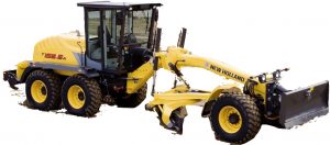
New Holland F106.6, F106.6A, F156.6, F156.6A Grader Factory Service & Shop Manual


New Holland F106.6, F106.6A, F156.6, F156.6A

MNHF106OPES.zip
Price: $29.99 USD

Complete workshop & service manual with electrical wiring diagrams for New Holland F106.6, F106.6A, F156.6, F156.6A Grader. It’s the same service manual used by dealers that guaranteed to be fully functional and intact without any missing page.

This New Holland F106.6, F106.6A Grader service & repair manual (including maintenance, overhaul, disassembling & assembling, adjustment, tune-up, operation, inspecting, diagnostic & troubleshooting…) is divided into different sections. Each section covers a specific component or system with detailed illustrations. A table of contents is placed at the beginning of each section. Pages are easily found by category, and each page is expandable for great detail. The printer-ready PDF documents work like a charm on all kinds of devices.

“604.13.567.pdf”
New Holland F106.6, F106.6A Grader Service Manual
Print No. 604.13.567 English III – 2005
579 pages

— — — — — — — — — — — — — — — — — — — — —

“87726937A”
New Holland F106.6, F106.6A, F156.6, F156.6A Grader Service Manual
Print No. 87726937A English Edition 12/2007
664 pages

EXCERPT:

F106.6 / F106.6A ATTACHMENT
6.1 CENTRAL ATTACHMENT
6.1.1 REMOVAL – INSTALLATION
Removal
DANGER
Lift and handle all heavy parts with a lifting device of appropriate capacity.
Make sure that groups or parts are held by appropriate slings and hooks.
Make sure that no bystanders are in the vicinity of loads to be lifted.
Proceed as follows:
– move the central attachment sideways, then rest it on the ground by actuating the appropriate cylinders;
– disconnect hydraulic pipes (1) of the front frame from the centre joint, from the swing motor and the brake valves, extract them from guide (2) on the tow bar and place them in a position so that they do not interfere with subsequent operations;
– remove the securing screws and disconnect eyes (3) of the lifting cylinder and the swivelling cylinder from the ball heads on the central attachment, recovering the adjusting shims;
– remove the four securing screws and separate securing plate (4) from the central attachment ball joint;
– support adequately with a cable and hoist, the central attachment complete with blade and ripper (opt.) then remove it using the hoist as required;
– disconnect hydraulic pipes (5) of the swivelling cylinder, support it adequately with a cable and hoist, then remove the four securing screws (6) and remove the cylinder;
– disconnect lifting cylinder hydraulic pipes (7);
– support adequately the lifting cylinder with a cable and hoist, then remove the four securing screws (8) and remove the cylinder;
– repeat the operation for the other lifting cylinder;

Posted on

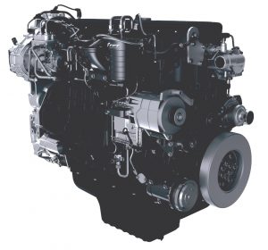
CNH/New Holland/Case Equipment Engines Factory Service & Shop Manual


Pages from 604.13.649 – 4HK1-6HK1 (Isuzu) Engines Workshop Manual (E385)

MCNHNHENGOPES.zip
Price: $29.99 USD

Complete workshop & service manual with electrical wiring diagrams for CNH/New Holland/Case Equipment Engines. It’s the same service manual used by dealers that guaranteed to be fully functional and intact without any missing page.

This CNH/New Holland/Case Equipment Engines service & repair manual (including maintenance, overhaul, disassembling & assembling, adjustment, tune-up, operation, inspecting, diagnostic & troubleshooting…) is divided into different sections. Each section covers a specific component or system with detailed illustrations. A table of contents is placed at the beginning of each section. Pages are easily found by category, and each page is expandable for great detail. The printer-ready PDF documents work like a charm on all kinds of devices.

FILELIST:
6-47950NA – 668T_M2 & 668T_E2 Engines Service Manual.pdf
6-49370NA – 4TAA-4502 & 6TAA-6802 Engines Service Manual.pdf
6-74500NA – 445_M2, 445T_M2 & 668T_M2 Series 2 Engines Service Manual.pdf
604.13.582 – F4BE0454B-F4BE0484D-F4BE0484E-F4BE0684B-F4BE0684M (E145-E175-E195-E215-E245 & MH2.6-MH3.6-MH4.6-MH Plus C) Repair Manual.pdf
604.13.612 – F4GE0454C, F4GE0484G Engines Repair Manual (for LB90.B – LB95.B – LB110.B – LB115.B).pdf
604.13.639 – F4GE0484E-F4GE0684F-F4HE0684J-F4AE0684K-F4AE0684L Engines Repair Manual.pdf
604.13.649 – 4HK1-6HK1 (Isuzu) Engines Workshop Manual (E385).pdf
604.13.654 – 4HK1-6HK1 (Isuzu) Engine Troubleshooting Manual (E385 Tier 3) .pdf
604.13.689 – 667TA_EEG-667TA_EEC-667TA_EBF-667TA_EED-667TA_EBD Engines (E265-E305, D180LGP-D180STD, W170-W190) Repair Manual.pdf
604.13.694 – F4GE0404B-F4GE0454C-F4GE0484G Engines (LM1330(Turbo)-LM1333(Turbo)-LM1340Turbo-LM 1343Turbo-LM1345Turbo-LM1443Turbo-LM 1445Turbo-LM1745Turbo) Repair Manual.pdf
84392403 – F4DFE613(A)(B)(C)(D)(G)(H)(J)(K)(L)(I)(G)(H)(J)(K)(P)(R)(X)(Y) Engines Service Manual.pdf
84465357 – F5AE9454(A)(D)(J)(L)_F5AE9484(A)(B)(G)(K)_F5CE5454(B)(C)(G)_F5CE9454(C)(E)(G)_F5CE9484(C)(E) Service Manual.pdf.pdf
84496807 – F5DFL413(A)(B)(C)(D) & F5HFL413(A)(B)(C) Tier 4a Engines Service Manual.pdf
84532047A (Suppl. to Service Manual 84527569A) – E385C (Hino) Diesel Engine Service Manual.pdf
87458412NA – NEF F4CE0354A Engines Repair Manual (334T_M2).pdf
87476950A – F2CE9684-F3AE9684 (CNH Cursor) Tier 3 Repair Manual.pdf
87519804NA – 667TA_EEG, 667TA_EEC, 667TA_EBF, 667TA_EED, 667TA_EBJ, 667TA_EDJ service manual.pdf
87630273NA – F4GE9454H_F4GE9454J_F4GE9484D_F4HE9484A_F4HE9484C Engine Backhoe Loader Repair Manual.pdf
87659057A – CNH NEF F4CE-F4DE-F4GE-F4HE Tier 3 4 Cylinders, Mechanical Injection & Electronic Common Rail Repair Manual.pdf
87659057A – NEF F4CE-F4DE-F4GE-F4HE Tier 3 (F4CE9484-F4DE9484-F4GE9484-F4HE9484) (4 Cylinders, Mechanical & Electronic Drive Common Rail) Repair Manual.pdf
87704086A – NEF F4CE-F4DE-F4GE-F4HE Tier 3 (6 Cylinders, Mechanical & Electronic Drive Common Rail) (F4CE9684-F4DE9684-F4DE9687-F4GE9684-F4HE9684-F4HE9687) Repair Manual.pdf
87736548A – F5C-F5A Tier III (Structural & Non Structural Version) (F5AE9484_F5AE9454_F5CE9484_F5CE9454_F5CE5454) Repair Manual.pdf
CNH Common Rail NEF Engines Training (F4AE 0684F*D101-155kW TAA).pdf
CNH NEF Tier 3 Engine Training (Shared Services) for Loader-Backhoe Case 580-590-695 SR2 Series.pdf
P1C32N001GB – Iveco-CNH CNG NEF Series Industrial applications N60 (N60 ENT G) Technical & Repair manual.pdf
P2D32F005E – Iveco-CNH F32 Tier 3 Series Industrial application F32 MNS & F32 MNT Technical & Repair Manual.pdf
P2D32N003E – Iveco-CNH NEF Tier 3 Series Industrial applications N45 & N67.X (N45 ENT.X, N45 MSS.X, N45 MNS.X, N45 MST.X, N45 MNT.X, N67 ENT.X, N67 ERT.X, N67 MRT.X, N67 MNT.X) Technical & Repair Manual.pdf
P2D32N003GB – Iveco-CNH NEF Tier 3 Series Industrial applications N45 ENT, N67 ENT Workshop Manual Technical & Repair Manual.pdf
P2D32V001E – Iveco-CNH Vector 8 Industrial applications Technical & Repair Manual.pdf
P4D32N001E – Iveco-CNH NEF Tier 2 Power Generation application N45 & N60 & N67 (GE_GS NEF 45M-60M-75M-85M-100M-125M-130M-160M-200E Technical & Repair Manual.pdf
P4D32N003E – Iveco-CNH NEF Tier 3 Series G-Drive applications N45 & N67 (NEF45 SM1X, NEF45 SM2X, NEF67 TE1X, NEF67 TE2X, NEF67 TM1X) Technical & Repair Manual.pdf
47597684 – Service Manual NEF Tier 3 Engines [F4CE(9484)(9487A_N)(9684) & F4DE(9484)(9684B_M)(9687) & F4GE(9484_C)(9684) & F4HE(0484G)(9484_C)(9687_G)].pdf

EXCERPT:
Contents
INTRODUCTION
HYDRAULIC, PNEUMATIC, ELECTRICAL, ELECTRONIC SYSTEMS A
ELECTRICAL POWER SYSTEM . . . . . . . A.30.A
ENGINE AND PTO IN ……. B
ENGINE . . . . . B.10.A
FUEL AND INJECTION SYSTEM. . . . . . . B.20.A
AIR INTAKE SYSTEM . . . . . B.30.A
EXHAUST SYSTEM. . . . . . . B.40.A
ENGINE COOLANT SYSTEM . . . . . . . . . . B.50.A
EXHAUST SYSTEM Emissions control . . . . . . . . B.40.B
LUBRICATION SYSTEM . . . . . . . . . B.60.A
STARTING SYSTEM . . . . . . B.80.A

HYDRAULIC, PNEUMATIC, ELECTRICAL, ELECTRONIC SYSTEMS – ELECTRICAL POWER SYSTEM
Alternator – Remove
Prior operation:
Fan and drive Belt – Remove (B.50.A)
1. Remove the cables from the back of the alternator.
2. Remove the retaining bolts (2) securing the alternator (1) to the support.
3. Remove the alternator (1).
ALTERNATOR 1
Next operation:
Alternator – Install (A.30.A)
Alternator – Install
Prior operation:
Alternator – Remove (A.30.A)
1. Install the alternator (1) and tighten the bolts (2) to the specified torque.
2. Connect the positive and negative cables onto the back of the alternator.
ALTERNATOR 1
Next operation:
Fan and drive Belt – Install (B.50.A)

Posted on

New Holland Kobelco E485, E485B, E805 Hydraulic Excavator Factory Service & Shop Manual


New Holland E485, E485B

MNHE485OPES.zip
Price: $29.99 USD

Complete workshop & service manual with electrical wiring diagrams for New Holland Kobelco E485, E485B, E805 Hydraulic Excavator. It’s the same service manual used by dealers that guaranteed to be fully functional and intact without any missing page.

This New Holland Kobelco E485, E485B, E805 Hydraulic Excavator service & repair manual (including maintenance, overhaul, disassembling & assembling, adjustment, tune-up, operation, inspecting, diagnostic & troubleshooting…) is divided into different sections. Each section covers a specific component or system with detailed illustrations. A table of contents is placed at the beginning of each section. Pages are easily found by category, and each page is expandable for great detail. The printer-ready PDF documents work like a charm on all kinds of devices.

“604.13.684.pdf”
New Holland / Kobelco E485 (Repowering) Hydraulic Excavator Worksop Manual
Print No. 604.13.684
Edition – February 2006
985 pages

— — — — — — — — — — — — — — — — — — — — —

“87475986A.pdf”
New Holland / Kobelco E485B Hydraulic Excavator Service Manual
1,101 pages
Print No. 87475986A
Edition – March 2008

“604.13.445 – New Holland Kobelco E805 Crawler Excavators Workshop Manual.pdf”

— — — — — — — — — — — — — — — — — — — — —

“87475986A – Crawler Excavator E485B Service Repair Manual.pdf”

EXCERPT:

SWING DEVICE

DESCRIPTION
1. The rotary group of the swing motor consists of a cylinder (24) which is integral with the drive shaft and nine piston assy (7) arranged in the cylinder bores. The cylinder (24) is supported by bearings (3) (22) on both ends.
Each piston assy (7) is guided by a return plate (6) and retaining spring (4) so as to slide smoothly on the cam plate (5).
The balance plate (21) is forced against the end of the cylinder by the force of the disc spring (18) and the hydraulic force acting on the bushing (20).
A mechanical brake is installed between the cylinder exterior and the housing (25).
A relief valve to cushion hydraulic shock and a backup valve to prevent cavitation are built in to the cover (32).
2. The reduction gear system consists of two stage planetary gears. The system decelerates high-speed rotary motion of the swing motor and coverts it to low-speed large-torque motion in order to rotate the pinion shaft.

Posted on

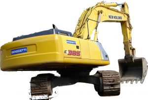
New Holland Kobelco E385/E385B/E385BLC Hydraulic Excavator Factory Service & Shop Manual


INSTANT DOWNLOAD


Complete workshop & service manual with electrical wiring diagrams for New Holland/Kobelco E385, E385B, E385BLC Hydraulic Excavator Hydraulic Excavator. It’s the same service manual used by dealers that guaranteed to be fully functional and intact without any missing page.

This New Holland/Kobelco E385, E385B, E385BLC Hydraulic Excavator service & repair manual (including maintenance, overhaul, disassembling & assembling, adjustment, tune-up, operation, inspecting, diagnostic & troubleshooting…) is divided into different sections. Each section covers a specific component or system with detailed illustrations. A table of contents is placed at the beginning of each section. Pages are easily found by category, and each page is expandable for great detail. The printer-ready PDF documents work like a charm on all kinds of devices.

FILELIST:
bonus_material
604.13.649 – New Holland_Kobelco E385 Hydraulic Excavator_Isuzu 4HK1-6HK1 Engine Worksop Manual.pdf
604.13.654 – New Holland_Kobelco E385 Hydraulic Excavator_Isuzu 4HK1-6HK1 Engine Troubleshooting Manual.pdf
604.13.679 – New Holland_Kobelco E385 (Tier 3) Hydraulic Excavator Worksop Manual.pdf
84268151 – New Holland_Kobelco E385B (ROPS Tier 3) Hydraulic Excavator Parts Catalog.pdf
84268157 – New Holland_Kobelco E385B (ROPS Tier 3) Hydraulic Excavator Operator’s Manual.pdf
84392431A – New Holland_Kobelco E385B (ROPS Tier 3) Hydraulic Excavator Service Manual.pdf
87709281A – New Holland_Kobelco E385B Hydraulic Excavator Worksop Manual.pdf
604.13.679 – New Holland Kobelco E385 Tier 3 Workshop Manual.pdf
87731197 – New Holland E385B, E385BLC Hydraulic Excavator Shop Manual.pdf
87731198 – New Holland E385B, E385BLC (HS Engine) Hydraulic Excavator Shop Manual.pdf
604.13.679 – New Holland Kobelco E385 Tier 3 Workshop Manual.pdf
87731197 – New Holland E385B, E385BLC Hydraulic Excavator Shop Manual.pdf
87731198 – New Holland E385B, E385BLC (HS Engine) Hydraulic Excavator Shop Manual.pdf

EXCERPT:

HYDRAULIC PUMP ASSY E385B

Operation

The pump assy is equipped with two pumps arranged on the same axis that are connected with gear (116) and distribute the rotating power to the gear trains on a different axis. Thus the engine rotation is transmitted to front shaft (111) that drives the two pumps and, at the same time, drives the pilot gear pump arranged on another shaft.

The pump assy consists largely of:
– the rotary group, the main part of the pump that makes rotary on;
– the swash plate group that changes the delivery rate;
– the valve block group that selects between oil suction and delivery;
– the PTO group that transmits the drive power to the gear pump.

ROTARY GROUP

The rotary group consists of shaft (111), cylinder block (141), piston (151), shoe (152), plate (153), spherical bushing (156), and cylinder spring (157). The shaft is supported by bearings (123) and (124) at its both ends. The shoe, which is caulked to the piston, forms a spherical joint and relieves it of thrust force that is generated by load pressure.

Further, the piston is provided with a pocket so it moves lightly on shoe plate (211), taking hydraulic balance.

The sub group of the piston-shoe is pressed against the shoe plate by the cylinder spring, via the retainer plate and the spherical bushing, so that it moves smoothly over the shoe plate. The cylinder blocks (141) are also pressed against valve plates (313) or (314) by the action of cylinder spring (157).


INSTANT DOWNLOAD