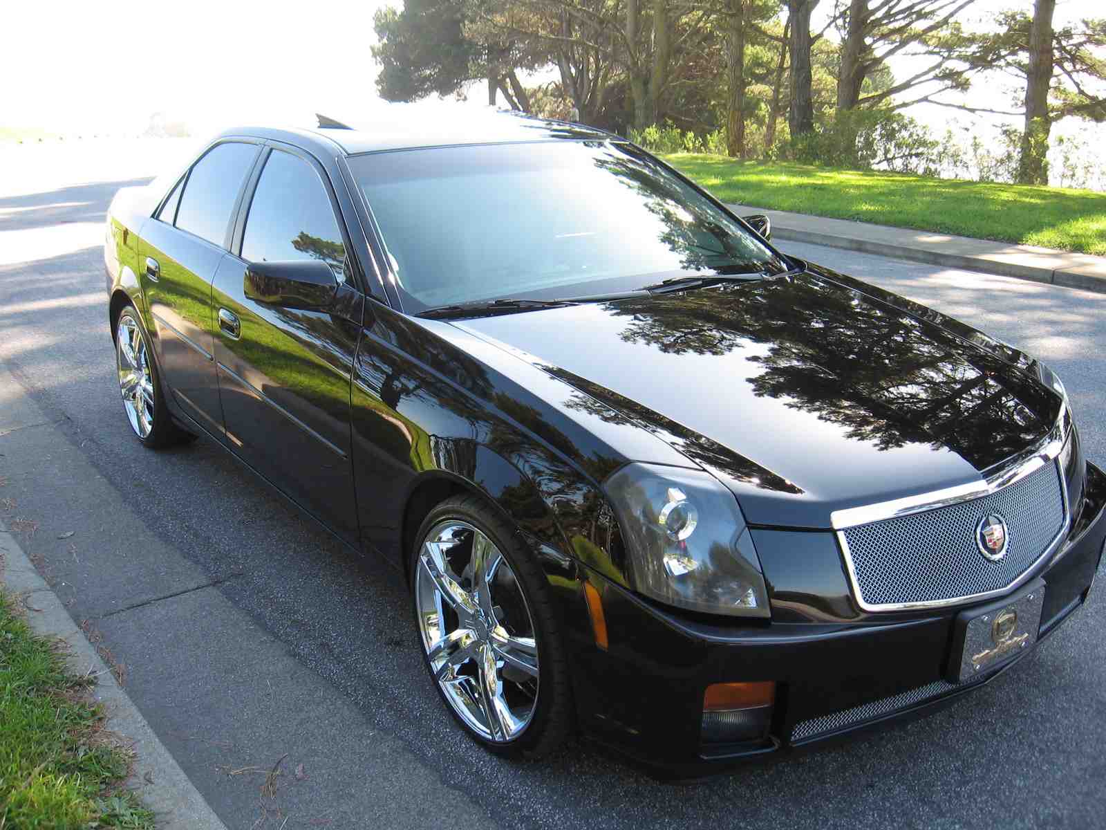
Complete digital workshop service and repair manual written for the Cadillac CTS; Production model years: 2003 2004 2005. All styles covered (all models, and engines). It is in the cross-platform PDF document format so that it works like a charm on all kinds of devices.
This QUALITY manual is 100% COMPLETE and INTACT, no MISSING/CORRUPT pages/sections to freak you out! Buy from responsible seller and get INSTANT DOWNLOAD now without wasting your hard-owned money on uncertainty or surprise; this manual is exactly as described.
PRODUCT DETAILS:
Total Pages: 10,007 pages
File Format: PDF (Windows & Mac & Linux)
Language: English
Delivery: instant download link displayed on checkout page & emailed to you after payment
Protection: DRM-free; without any restriction
Printable: Yes
This COMPLETE workshop service repair manual includes:
* Detailed sub-steps expand on repair procedure information
* Notes, cautions and warnings throughout each chapter pinpoint critical information.
* Numbered instructions guide you through every repair procedure step by step.
* Bold figure number help you quickly match illustrations with instructions.
* Detailed illustrations, drawings and photos guide you through every procedure.
* Enlarged inset helps you identify and examine parts in detail.
* Numbered table of contents easy to use so that you can find the information you need fast.
* This manual also makes it easy to diagnose and repair problems with your machines electrical system.
* Troubleshooting and electrical service procedures are combined with detailed wiring diagrams for ease of use.
* COMPLETE, Absolutely No Missing Pages!
* Customer Satisfaction GUARANTEED!
EXCERPT (2003-2005 Cadillac CTS Service/Repair Manual):
AIR CONDITIONING (A/C) SYSTEM PERFORMANCE TEST (3.6L (LY7), 2.8L (LPl))
Test Description
This test measures the operating efficiency of the A/C system under the following conditions:
The current ambient air temperature
The current relative humidity
The high side pressure of the A/C system
The low side pressure of the A/C system
The temperature of the air being discharged into the passenger compartment
The numbers below refer to the step numbers on the diagnostic table.
1: This step determines if the A/C system has at least the minimum refrigerant charge
required to operate the system without damage.
2: This step measures the performance of the A/C system
3: This step is to allow for vehicle variations as well as high ambient temperatures.
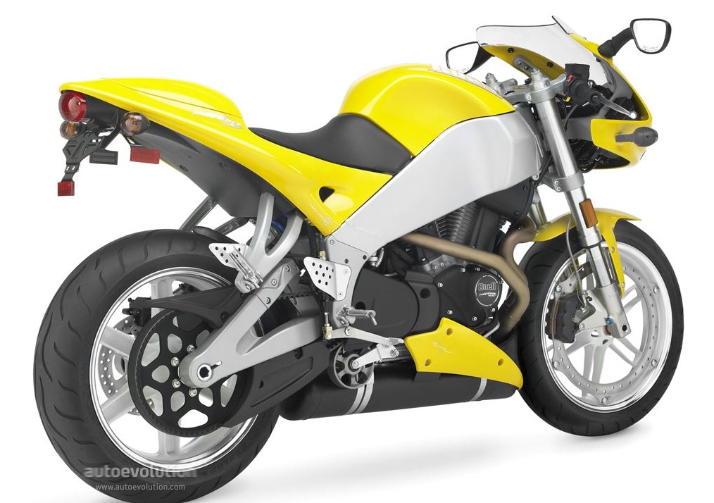
Complete digital workshop service and repair manual written for the 2003 Buell XB9R Firebolt Motorcycle. All styles covered (all models, and engines). It is in the cross-platform PDF document format so that it works like a charm on all kinds of devices.
This QUALITY manual is 100% COMPLETE and INTACT, no MISSING/CORRUPT pages/sections to freak you out! Buy from responsible seller and get INSTANT DOWNLOAD now without wasting your hard-owned money on uncertainty or surprise; this manual is exactly as described.
PRODUCT DETAILS:
Total Pages: 673 pages
File Format: PDF (Windows & Mac & Linux)
Language: English
Delivery: instant download link displayed on checkout page & emailed to you after payment
Protection: DRM-free; without any restriction
Printable: Yes
This COMPLETE official full workshop service repair manual for 2003 Buell XB9R Firebolt Sport Bike includes:
* Detailed sub-steps expand on repair procedure information
* Notes, cautions and warnings throughout each chapter pinpoint critical information.
* Numbered instructions guide you through every repair procedure step by step.
* Bold figure number help you quickly match illustrations with instructions.
* Detailed illustrations, drawings and photos guide you through every procedure.
* Enlarged inset helps you identify and examine parts in detail.
* Numbered table of contents easy to use so that you can find the information you need fast.
* This manual also makes it easy to diagnose and repair problems with your machines electrical system.
* Troubleshooting and electrical service procedures are combined with detailed wiring diagrams for ease of use.
* COMPLETE, Absolutely No Missing Pages!
* Official Service INFORMATION You Can Count On!
* Customer Satisfaction GUARANTEED!
EXCERPT (2003 Buell XB9R Firebolt Motorbike Service/Repair Manual):
If engine is removed from chassis, do not lay engine on primary side. Placing engine on primary side will damage clutch cable and fitting. If fitting is damaged, clutch cable must be replaced.
Always connect positive battery cable first. If the positive cable should contact ground with the negative cable installed, the resulting sparks may cause a battery explosion which could result in death or serious injury.
Pull up on seat to verify that it is properly secured, front and rear. A loose seat may shift during vehicle operation and startle the rider, possibly causing loss of vehicle control resulting in death or serious injury.
At this point it will be necessary to install the oil lines. It is important to follow this procedure to ensure correct orientation of oil lines in order to establish the proper clearances needed between the oil lines and varied components on the vehicle.
1999-2000 Buell X1 Lightning Motorcycle Workshop Repair & Service Manual
MBULX19900OPES.zip
Price: $9.99 USD
1999-2000 Buell X1 Lightning Motorcycle Workshop Repair & Service Manual
Complete digital workshop service and repair manual written for the Buell X1 Lightning Motorcycle; Production model years: 1999 2000. All styles covered (all models, and engines). It is in the cross-platform PDF document format so that it works like a charm on all kinds of devices.
This QUALITY manual is 100% COMPLETE and INTACT, no MISSING/CORRUPT pages/sections to freak you out! Buy from responsible seller and get INSTANT DOWNLOAD now without wasting your hard-owned money on uncertainty or surprise; this manual is exactly as described.
PRODUCT DETAILS:
Total Pages: more than 538 pages
File Format: PDF (Windows & Mac & Linux)
Language: English
Delivery: instant download link displayed on checkout page & emailed to you after payment
Protection: DRM-free; without any restriction
Printable: Yes
This COMPLETE official full workshop service repair manual includes:
* Detailed sub-steps expand on repair procedure information
* Notes, cautions and warnings throughout each chapter pinpoint critical information.
* Numbered instructions guide you through every repair procedure step by step.
* Bold figure number help you quickly match illustrations with instructions.
* Detailed illustrations, drawings and photos guide you through every procedure.
* Enlarged inset helps you identify and examine parts in detail.
* Numbered table of contents easy to use so that you can find the information you need fast.
* This manual also makes it easy to diagnose and repair problems with your machines electrical system.
* Troubleshooting and electrical service procedures are combined with detailed wiring diagrams for ease of use.
* COMPLETE, Absolutely No Missing Pages!
* Official Service INFORMATION You Can Count On!
* Customer Satisfaction GUARANTEED!
EXCERPT (1999-2000 Buell X1 Lightning Motorbike Service/Repair Manual):
1. Position motorcycle on a suitable lift and position REAR WHEEL SUPPORT
STAND (Part No. B41174) under swing arm. Secure motorcycle to lift.
2. Disconnect negative battery cable.
3. Remove seat and fuel tank. See appropriate service manual, Section 4 for
procedure
4. Remove air box cover (and left fairing lower on S3Ts) and filter box.
5. Remove two nuts and 2 socket head screws from air cleaner backplate and front
isolator mount.
6. Position floor jack under engine under front shock mount to support engine.
7. Remove and discard isolator locknut and remove bolt, two washers and D
washer.
8. Remove and discard two bolts and washers from left and right side of front
isolator mount.
9. Remove front isolator mount from left side of motorcycle.
10. Clean residual lactate from threads in engine with a suitable nonflammable
solvent and dry with compressed air.
11. Apply LACTATE THREAD-LOCKER 271 (red) to threads of new front isolator
mount bolts.
12. Apply a thin film of clean HD 20W50 engine oil to both sides of new thick
washers and to bottom of bolt heads. Exercise caution to avoid mixing oil on
washers with lactate on bolts.
13. Position new front isolator mount and secure with two new front bolts with
new thick washers. Tighten bolts 60 ft-Ibs (81 Nm) initially and then loosen each
bolt full turn. Tighten bolts again to 60 ft-Ibs (81 Nm). Make sure flat on D washer
remains oriented to front of motorcycle while tightening bolt.
14. Position washer between front isolator mount and isolator. Install bolt, washer,
D washer and new locknut.
15. Making sure flat on D washer stays oriented to front of bike, tighten bolt to 100
ft-Ibs (135.6 Nm)
16. Apply THREAD-LOCKER 243 (blue) to threads of air-box screws.
Install air box screws to air box and isolator mount. Install locknuts to screws.
17. Install air cleaner filter box and cover.
18. Connect negative battery cable.
19. Install fuel tank and seat.
The 2000 Model Year ECM software and overheat indication are explained in the 1999/2000 Buell Service Manuals for the
X1 and S3/S3T.
On 2000 Model Year DDFI equipped models (X1 and S3/S3T), as part of the standard software in the ECM, the check engine lamp will blink during operation to warn of potentially damaging engine temperatures. If the key is in the ON position and the check engine lamp is blinking, this indicates that the engine is approaching a potentially damaging temperature.
While this condition is in effect, the ECM will automatically reduce engine power to assist in cooling the engine down to normal operating temperature. The check engine lamp will blink until the engine has cooled to normal operating temperature.
The rider may experience this condition during extended high speed operation with high ambient temperatures or during extended periods at idle. Inform customers of this feature and explain that it protects the engine from overheating damage and that if the check engine lamp blinks during high speed operation, normal operation may be continued without fear of engine overheating damage, but slowing down slightly will assist engine cooling and make full power available again sooner. If the check engine lamp blinks during extended periods at idle, and if there is no way of increasing the flow of air across the engine, the motorcycle should be shut down and allowed to cool.
Complete digital workshop service and repair manual written for the 1996 Buell S1 Lightning Motorcycle. All styles covered (all models, and engines). It is in the cross-platform PDF document format so that it works like a charm on all kinds of devices.
This QUALITY manual is 100% COMPLETE and INTACT, no MISSING/CORRUPT pages/sections to freak you out! Buy from responsible seller and get INSTANT DOWNLOAD now without wasting your hard-owned money on uncertainty or surprise; this manual is exactly as described.
PRODUCT DETAILS:
Total Pages: 371 pages
File Format: PDF (Windows & Mac & Linux)
Language: English
Delivery: instant download link displayed on checkout page & emailed to you after payment
Protection: DRM-free; without any restriction
Printable: Yes
This COMPLETE official full workshop service repair manual for 1996 Buell S1 Lightning Sport Bike includes:
* Detailed sub-steps expand on repair procedure information
* Notes, cautions and warnings throughout each chapter pinpoint critical information.
* Numbered instructions guide you through every repair procedure step by step.
* Bold figure number help you quickly match illustrations with instructions.
* Detailed illustrations, drawings and photos guide you through every procedure.
* Enlarged inset helps you identify and examine parts in detail.
* Numbered table of contents easy to use so that you can find the information you need fast.
* This manual also makes it easy to diagnose and repair problems with your machines electrical system.
* Troubleshooting and electrical service procedures are combined with detailed wiring diagrams for ease of use.
* COMPLETE, Absolutely No Missing Pages!
* Official Service INFORMATION You Can Count On!
* Customer Satisfaction GUARANTEED!
EXCERPT (1996 Buell S1 Lightning Motorbike Service/Repair Manual):
TRANSMISSION CASE
GENERAL
The rear compartment of the left and right crankcase halves form the transmission case. An access cover (door) allows removal of transmission components without removing the engine or disassembling (splitting) the crankcase.
REMOVAL
1. Raise rear wheel off floor using REAR WHEEL SUPPORT STAND (Part No. B-41174).
2. Remove rear fender. See FENDERS in Section 2.
3. See Figure 6-12. Loosen rear axle nut (metric). Reduce tension on secondary drive belt by turning axle adjuster nuts on each side of swingarm an equal number of turns counterclockwise. Move rear wheel as far forward as possible.
4. Remove muffler. See EXHAUST SYSTEM in Section 2. Place a drain pan under the engine. Remove drain plug and drain lubricant from primary drive/transmission.
5. Remove swingarm/drive support screws and retaining nut. Remove sprocket cover, washer and spacer.
6. See Figure 6-13. Place transmission in first gear. Remove two socket head screws (5) and lockplate (4).
Figure 6-12. Secondary Drive Belt Adjustment b0249x6x
1 CAUTION
Transmission sprocket nut has left-hand threads. To prevent damage, turn nut clockwise to loosen and remove from main drive gear shaft.
7. Remove transmission sprocket nut (3) from main drive gear shaft (1).
8. Remove secondary drive belt from transmission sprocket (2). Remove transmission sprocket from main drive gear shaft (1).
9. Remove primary cover. See PRIMARY CHAIN on page 6-3.
10. Remove clutch assembly, primary chain and engine sprocket. See PRIMARY DRIVE/CLUTCH on page 6-10.
11. See Figure 6-14. Lock transmission in gear. Remove countershaft TORX screw and retainer.
12. See Figure 6-15. Detach spring (1) from groove in post (2).
13. Remove retaining ring (10) and detent plate (9). You will need to use a new retaining ring for installation.
14. Remove two locknuts (3) and washers (11) which attach shifter shaft assembly (6) to studs at transmission case. Remove shifter shaft assembly.
15. Remove five access door bolts (7) and washers (8). Remove transmission assembly by pulling it straight outward, away from transmission case.
CLEANING, INSPECTION AND REPAIR
Thoroughly clean transmission compartment with cleaning solvent. Blow parts dry with compressed air. Inspect parts to determine if any must be replaced. Replace all parts that are badly worn or damaged.
Neutral Indicator Switch
See Figure 6-16. The neutral indicator switch is threaded into the transmission portion of the right crankcase half. See NEUTRAL INDICATOR SWITCH in Section 7 for testing, removal and installation procedures.
1994-2007 BMW Wiring Diagram System (Searchable, Printable)
MBMWWDS9407OMMK
Price: $14.99 USD
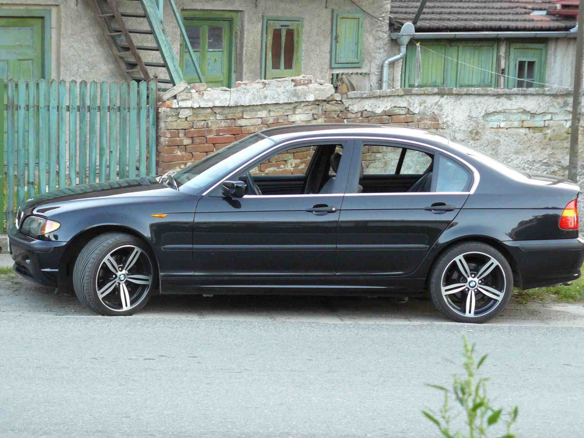
1994-2007 BMW Wiring Diagram System (Searchable, Printable)
Complete digital workshop wiring diagram manual written for the BMW Vehicles; Production model years: 1994 1995 1996 1997 1998 1999 2000 2001 2002 2003 2004 2005 2006 2007. All styles covered (all models, and engines). This QUALITY manual is 100% COMPLETE and INTACT, no MISSING/CORRUPT pages/sections to freak you out! Buy from responsible seller and get INSTANT DOWNLOAD now without wasting your hard-owned money on uncertainty or surprise; this manual is exactly as described.
PRODUCT DETAILS:
Total Pages: thousands pages
File Format: HTML/PNG et
Language: CH/DE/EN/FR/GR/IT/JA/KO/NI/PO/RU/SPA/SV/TH/TR/US
Delivery: instant download link displayed on checkout page & emailed to you after payment
Protection: DRM-free; without any restriction
Printable: Yes
BMW Wiring Diagram System (WDS, 2007/09)
Model 7 E38 03/94 – 09/98
Model 7 E38 from 09/98
Model 5 E39 12/95 – 09/98
Model 5 E39 from 09/98
Model 3 E46
Model 1 E81 E82 E87 E88
Model 3 E90 E91 E92 E93
Model 5 E60 E61
Model 6 E63 E64
Model 7 E65 E66 E68
Model X3 E83
Model X5 E53
Model X5 E70
Model Z4 E85 E86
Model Z8 E52
This COMPLETE official full workshop service repair manual includes:
* Detailed sub-steps expand on repair procedure information
* Notes, cautions and warnings throughout each chapter pinpoint critical information.
* Numbered instructions guide you through every repair procedure step by step.
* Bold figure number help you quickly match illustrations with instructions.
* Detailed illustrations, drawings and photos guide you through every procedure.
* Enlarged inset helps you identify and examine parts in detail.
* Numbered table of contents easy to use so that you can find the information you need fast.
* This manual also makes it easy to diagnose and repair problems with your machines electrical system.
* Troubleshooting and electrical service procedures are combined with detailed wiring diagrams for ease of use.
* COMPLETE, Absolutely No Missing Pages!
* Official Service INFORMATION You Can Count On!
* Customer Satisfaction GUARANTEED!
MBMWWDS9407OMMK
Price: $14.99 USD
EXCERPT (1994-2007 BMW Wiring Diagram System Service/Repair Manual):
Closed-circuit (standby) current cutout
The electrical closed circuit cutout function switches off loads which consume closed circuit (standby) current at terminal 30. The closed circuit current cutout is controlled by the load cutout relay K72.
A voltage filter is additionally integrated in the relay K72 to filter the ripple of the electrical system. This filter is necessary for the motors of the steering column and seat memory.
The following systems are connected to the closed circuit current cutout:
•7 series, E38, up to model year 1996: Seat adjustment, rear head restraint adjustment, steering column adjustment and sun shade.
•7 series, E38, as of model year 1996: Seat/steering column memory
•5 Series, E39: Seat/steering column memory
The relay K72 is driven via terminal 15 and the “load cutout” signal from the general module of the ZKE III
Load cut-out signal
The load cutout signal is switched by the general module of the ZKE III.
When terminal R is switched on, B+ is switched from the general module to the relay K72. The general module switches off the B+ supply 16 minutes after switching off terminal R.
The relay is switched on again together with switching on terminal R or terminal 15 or, when a signal change takes place at an input of the ZKE III; e.g. opening a door, opening the front lid, unlocking a door.
When terminal 15 is switched on (signal at Pin 8 of relay K72) the closed circuit current cutout relay switches on the B+ supply for the connected loads irrespective of the status of the load cutout signal.
Symptom list in the case of complaints regarding the audio system
This symptom list contains radio complaints which are not caused by device malfunctions. Replacing the radio will not eliminate the problem.
Reception
Poor reception with radio BMW Business CD RDS (world device CD 43)
Cause: Incorrect reception area set.
Radios concerned: Business CD RDS (world set CD 43)
Situation: The Business radio CD RDS (world device CD43) is designed for all reception areas in the world. If the right reception area is not set in the radio menu ”AREA”, the result can be poor reception.
Action: Setting the reception area
Procedure: Initial commissioning of the radio (replacement device, new device)
•Fit replacement radio in vehicle and switch on radio.
•The message ”NO AREA” appears in the radio display (only during initial operation of the radio)
•Now switch to the required region (”Europe”, ”USA”, ”Canada”, ”OC+RDS”, ”Japan”).
a) On E46 radio and DIN unit with ”Station button 1”.
b) On E39 radio with first softkey (Station button 1).
•Now switch off radio (AREA is saved).
Procedure: Changing a reception area that has already been set
a) On E46 and E39 radios
•Switch on service mode (switch on radio and press ”m” button within 8 seconds)
•Now press the ”+ button” as many times as required until ”AREA” is displayed in the radio display.
•Use ”Station button 1” now to select the suitable AREA in the menu and switch off the radio (AREA is stored).
b) On DIN radio
Same procedure as for E46, E39 radio
On the DIN radio, depending on the set reception area, a CODE input might be necessary after the changeover.
Temporary reception cutout
Cause: Radio searches for better alternative frequency in the reception chain. Here the received station has to be interrupted briefly, which leads to gaps in reception.
Radios concerned: Reverse and Business
Note: RDS may be switched off in critical areas. In the case of the ”Professional” radio this search for alternative frequencies is carried out with a second receiver. This is the reason that there is no temporary cutout with this radio.
Temporary reception fall-off, lattice fence effect
Cause: Multipath reception fall-off – concept-related on VHF – multipath cancellation effect due to wave overlay.
Radios concerned: Reverse or if no aerial diversity is fitted.
Note: Can be remedied using aerial diversity (only in conjunction with Business and Professional)
Interference noise or crackle on classical music stations
Cause: Classical music stations often broadcast with low modulation in order to avoid distortion. As a result, interference is distinctly more discernible.
Radios concerned: All
Note: No corrective measures possible as the fault is caused by the broadcasting station.
RDS
The radio does not set better alternative frequencies on the stations stored under the station buttons.
Cause: Frequencies have been stored before the station name appears in the display or the station has no alternative frequencies.
Radios concerned: All
Note: When storing the station, wait until the station name appears in the display.
Radio does not set an alternative, better frequency. Only the frequency appears in the display.
Cause: RDS is switched off.
Radios concerned: All
Note: By pressing the RDS button, the station name appears in the display and a search is conducted automatically for the best alternative frequency.
In certain areas no alternative frequencies are found although they can be set with a manual search.
Cause: In areas that have stations with permanent regionalisation, alternative frequencies cannot be found when regional mode is switched on (REG=ON) if they have another regional identifier.
Radios concerned: All
Note: REG by pressing the RDS button for a longer period (display: REG=OFF) or switch off the REG button.
Receiver jumps of its own accord to another station (or several other stations)
Cause: The regional station function is switched off in the radio and the station being listened to broadcasts regional programmes.
Radios concerned: All
Note: REG by pressing the RDS button for a longer period (display: REG=OFF) or switch on the REG button.
Traffic information
Radio increases the volume of its own accord or following traffic information it no longer reverts to normal volume.
Cause: The station has forgotten to reset the traffic information identifier (TA) (common occurrence with private stations).
Radios concerned: All
Note: The old status can be restored by switching off the traffic information function (press TP).
The volume of traffic information increases several seconds before the actual message is received.
Cause: The station often broadcasts the traffic information identifier (TA) too early (a common practice in order to broadcast the time for traffic information memory).
Radios concerned: All
Note: No remedy; caused by the station.
Traffic information volume too loud
Cause: The traffic information volume can be varied during the announcement. The set volume is stored automatically.
Radios concerned: Business and Professional.
Note: During traffic report, set volume lower.
Minimum setting of traffic information volume too loud or too quiet.
Cause: Basic traffic information volume set too loud or too quiet.
Radios concerned: All
Note: Adapt basic volume as part of diagnosis procedure or in service mode.
Cassette / CD operation
Cassette playback too fast or too slow
Cause: Cassette has been recorded on a home unit with another speed (too slow or too fast)
Radios concerned: All
Note: Check playback using other cassettes.
During the music track search, the cassette does not stop between the tracks.
Cause: The breaks between the tracks are too short.
Radios concerned: All
Note: For the music track search, there must be breaks between the tracks of at least 4 seconds.
Cassette / CD operation is interrupted by the radio; unable to return to the cassette / CD operating condition.
Cause: The TP function is on and the station inadvertently broadcasts the traffic information identifier (TA). This interrupts the cassette / CD operation.
Radios concerned: All
Note: The old status can be restored by switching off the traffic information function (press TP).
Volume / speakers
Speed-dependent volume increase is too weak / too strong
Cause: Set speed dependent volume characteristic curve is not adapted to the vehicle.
Radios oncerned: All radios except of the Top HiFi System is fitted.
Note: Change the speed dependent volume (GAL) control setting in the DIS under service functions. GAL1 corresponds to the smallest volume increase, GAL4 or GAL6 are the greatest rises.
Speed-dependent volume is not increased
Cause: Top HiFi System fitted
Radios concerned: All E38 and E39 radios with Top HiFi System.
Note: In conjunction with the Top HiFi System, only one characteristic curve is permanently stored in the Top HiFi amplifier. The different GAL stages in the radio are not in operation.
Volume between two stations or between radio station and cassette or CD differs greatly on switching over.
Cause: Radio stations can broadcast at different modulation levels. The cassette or CD might have been recorded at a different volume.
Radios concerned: All
Note: Check playback using other stations, other cassettes or CDs.
Loudspeakers boom, rattle or do not produce the desired sound pattern
Cause: Loose speaker cables can strike body components or neighbouring body components can also vibrate.
Radios concerned: All
Note: Check cables over the entire length and fix with insulating tape as required. Attention should also be paid to ensuring that no neighbouring body components are able to vibrate.
Temporary failure of opposing speaker
Cause: Abrupt changeovers from stereo to mono give the impression that a loudspeaker fails.
Radios concerned: All
Note: In the event of audible interference in reception, reproduction is switched over from stereo to mono as such interference is perceived to be unpleasant in stereo.
Station storage
It is necessary to reprogram the stations when driving through different broadcasting areas.
Cause: The station with the strongest signal in the relevant area can be selected with the autostore function.
Radios concerned: Business and Reverse
Note: Activate autostore function by pressing and holding the FM button. Selection of station buttons in FMA mode.