Posted on

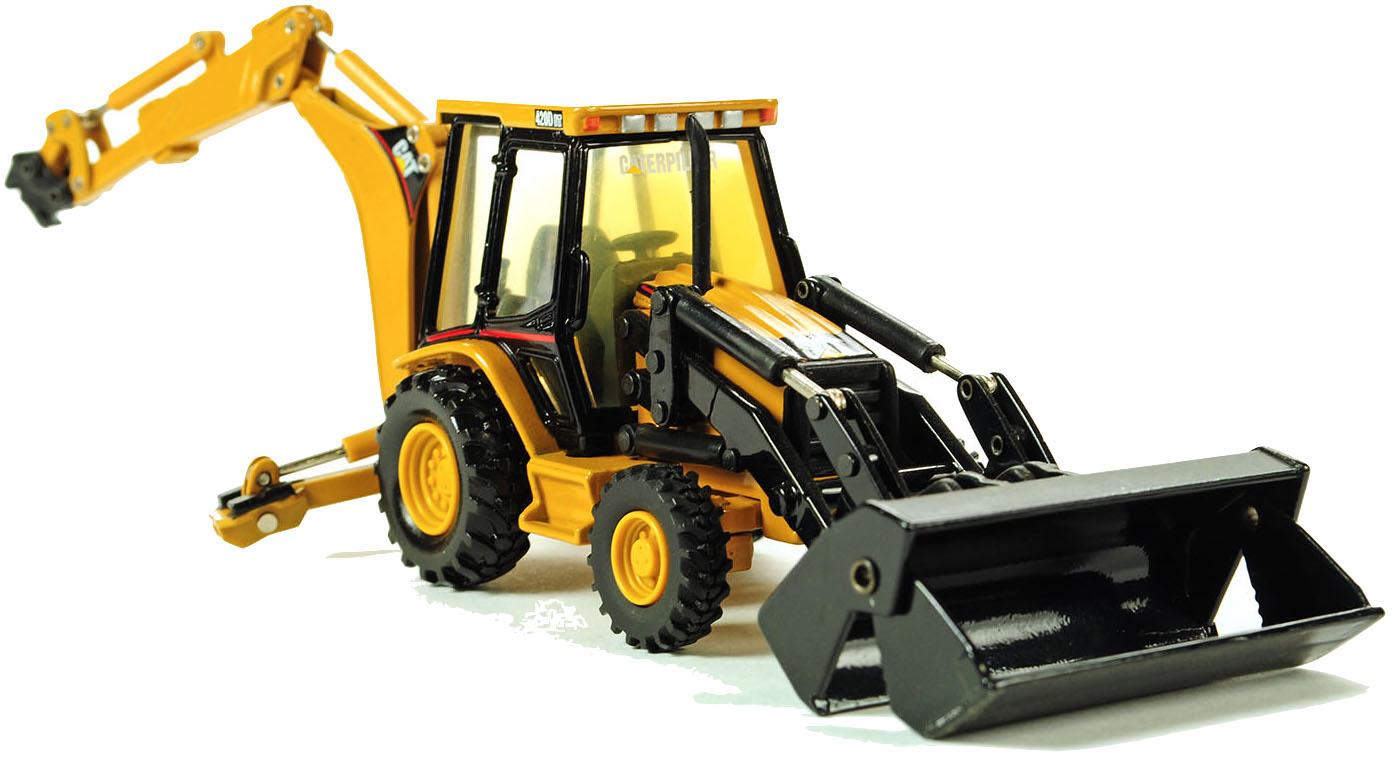
Caterpillar 416D, 420D, 424D, 428D, 430D, 432D, 438D, 442D Backhoe Loaders Factory Service & Shop Manual


Download Link

INSTANT DOWNLOAD

ADD TO CART

This Caterpillar 416D, 420D, 424D, 428D, 430D, 432D, 438D, 442D Backhoe Loaders service & repair manual (including maintenance, overhaul, disassembling & assembling, adjustment, tune-up, operation, inspecting, diagnostic & troubleshooting…) is divided into different sections. Each section covers a specific component or system with detailed illustrations. A table of contents is placed at the beginning of each section. Pages are easily found by category, and each page is expandable for great detail. The printer-ready PDF documents work like a charm on all kinds of devices.

MANUAL LIST:
SEBP3993 – Parts Manual (416D Backhoe Loader, Powered By 3054C Engine)
RENR3573 – Disassembly & Assembly (416D, 420D, 424D, 428D, 430D, 432D, 438D, 442D Backhoe Loaders Engine Supplement)
RENR3574 – Specifications (416D, 420D, 424D, 428D, 430D, 432D, 438D, 442D Backhoe Loaders Transmission (Direct Drive))
RENR3574 – Systems Operation (416D, 420D, 424D, 428D, 430D, 432D, 438D, 442D Backhoe Loaders Transmission (Direct Drive))
RENR3574 – Testing & Adjusting (416D, 420D, 424D, 428D, 430D, 432D, 438D, 442D Backhoe Loaders Transmission (Direct Drive))
RENR3576 – Specifications (416D, 420D, 424D, 428D, 430D, 432D, 438D and 442D Backhoe Loaders Axles, Differential and Brakes)
RENR3577 – Systems Operation (416D, 420D, 424D, 428D, 430D, 432D, 438D and 442D Backhoe Loaders Axles, Differential and Brakes)
RENR3577 – Testing & Adjusting (416D, 420D, 424D, 428D, 430D, 432D, 438D and 442D Backhoe Loaders Axles, Differential and Brakes)
RENR3578 – Disassembly & Assembly (416D, 420D, 424D, 428D, 430D, 432D, 438D, 442D Backhoe Loaders Power Train)
RENR3579 – Specifications (416D Backhoe Loader Hydraulic and Steering System)
RENR3580 – Systems Operation (416D Backhoe Loader Hydraulic and Steering System)
RENR3582 – Specifications (416D, 420D, 424D, 428D, 430D, 432D, 438D, 442D Backhoe Loaders Hydraulic & Steering System)
RENR3583 – Systems Operation (416D, 420D, 424D, 428D, 430D, 432D, 438D and 442D Backhoe Loaders Hydraulic and Steering System)
RENR3584 – Testing & Adjusting (416D, 420D, 424D, 428D, 430D, 432D, 438D and 442D Backhoe Loaders Hydraulic & Steering System)
RENR3585 – Disassembly & Assembly (416D, 420D, 424D, 428D, 430D, 432D, 438D and 442D Backhoe Loaders Machine Systems)
RENR3586 – Schematic (416D and 424D Backhoe Loader Hydraulic System)
RENR3587 – Schematic (416D, 420D, 424D, 428D, 430D, 432D, 438D, and 442D Backhoe Loaders Electrical System)
RENR6406 – Specifications (416D, 420, 430D Backhoe Loaders Axles, Differential and Brakes)
RENR6407 – Systems Operation (416D, 420D and 430D Backhoe Loaders Axles, Differential and Brakes)
RENR6407 – Testing & Adjusting (416D, 420D and 430D Backhoe Loaders Axles, Differential and Brakes)
RENR7781 – Schematic (416D, 420D, 424D, 428D, 430D, 432D, 442D, and 446D Backhoe Loader Electrical System)
RENR7785 – Disassembly and Assembly (416D, 420D, 424D, 428D, 430D, 432D, 442D Backhoe Loaders Engine Supplement)

EXCERPT:
4. Remove two bolts (7). Then, remove bottom seat cushion (8) .
5. Remove three bolts (10). Then, remove side cushion (9) .
6. Repeat Step 5 in order to remove the side cushion on the other side of the seat.
7. Remove the nut and bolt (12) that holds comfort ride sleeve (11) to the seat. Remove comfort ride sleeve (11) and bushing (14). Remove the nut and bolt (15) that holds seat belt retractor (13) to the seat. Remove seat belt retractor (13) .

Posted on

Caterpillar 414E, 416E, 420E, 422E, 428E, 430E, 432E, 434E, 442E, 444E Backhoe Loaders Factory Service & Shop Manual


Download Link

INSTANT DOWNLOAD

ADD TO CART


Complete workshop & service manual with electrical wiring diagrams for Caterpillar 414E, 416E, 420E, 422E, 428E, 430E, 432E, 434E, 442E, 444E Backhoe Loaders. It’s the same service manual used by dealers that guaranteed to be fully functional and intact without any missing page.

This Caterpillar 414E, 416E, 420E, 422E, 428E, 430E, 432E, 434E, 442E, 444E service & repair manual (including maintenance, overhaul, disassembling & assembling, adjustment, tune-up, operation, inspecting, diagnostic & troubleshooting…) is divided into different sections. Each section covers a specific component or system with detailed illustrations. A table of contents is placed at the beginning of each section. Pages are easily found by category, and each page is expandable for great detail. The printer-ready PDF documents work like a charm on all kinds of devices.

FILELIST:
RENR6473 – Specifications (420E, 430E, 432E, 434E, 442E, 444E Backhoe Loaders Transmission (Power Shift))
RENR6473 – Systems Operation (420E, 430E, 432E, 434E, 442E, 444E Backhoe Loaders Transmission (Power Shift))
RENR6473 – Testing & Adjusting (420E, 430E, 432E, 434E, 442E, 444E Backhoe Loaders Transmission (Power Shift))
RENR6474 – Specifications (414E, 416E, 420E, 422E, 428E, 430E, 432E, 434E, 442E, 444E Backhoe Loaders Transmission (Standard Shift))
RENR6474 – Systems Operation (414E, 416E, 420E, 422E, 428E, 430E, 432E, 434E, 442E, 444E Backhoe Loaders Transmission (Standard Shift))
RENR6474 – Testing & Adjusting (414E, 416E, 420E, 422E, 428E, 430E, 432E, 434E, 442E, 444E Backhoe Loaders Transmission (Standard Shift))
RENR6475 – Disassembly & Assembly (414E, 416E, 420E, 422E, 428E, 430E, 432E, 434E, 442E, 444E Backhoe Loaders Power Train)
RENR6476 – Specifications (414E, 416E, 420E, 422E, 428E, 430E, 432E, 434E, 442E, 444E Backhoe Loaders Axles, Differential and Brakes)
RENR6477 – Systems Operation (414E, 416E, 420E, 422E, 428E, 430E, 432E, 434E, 442E, 444E Backhoe Loaders Axles, Differential and Brakes)
RENR6477 – Testing & Adjusting (414E, 416E, 420E, 422E, 428E, 430E, 432E, 434E, 442E, 444E Backhoe Loaders Axles, Differential and Brakes)
RENR6478 – Specifications (414E, 416E, 420E, 422E, 428E, 430E, 432E, 434E, 442E, 444E Backhoe Loaders Hydraulic and Steering System)
RENR6479 – Systems Operation (416E, 422E and 428E Backhoe Loaders Hydraulic and Steering System)
RENR6479 – Testing & Adjusting (416E, 422E and 428E Backhoe Loaders Hydraulic and Steering System)
RENR6480 – Systems Operation (420E, 430E, 432E, 434E, 442E, 444E Backhoe Loaders Hydraulic and Steering System)
RENR6480 – Testing & Adjusting (420E, 430E, 432E, 434E, 442E, 444E Backhoe Loaders Hydraulic and Steering System)
RENR6481 – Schematic (420E, 430E, 432E, 434E, 442E, 444E Backhoe Loader Electrical System)
RENR6482 – Schematic (416E, 422E, 428E Backhoe Loader Hydraulic System)
RENR6483 – Schematic (420E, 430E Backhoe Loader Hydraulic System)
RENR6484 – Schematic (432E, 434E, 442E, 444E Backhoe Loader Hydraulic System)
RENR6485 – Disassembly & Assembly (414E, 416E, 420E, 422E, 428E, 430E, 432E, 434E, 442E, 444E Backhoe Loaders Machine Systems)
RENR6487 – Disassembly & Assembly (414E, 416E, 420E, 422E, 428E, 430E, 432E, 434E, 442E, 444E Backhoe Loaders Engine Supplement)
RENR6488 – Systems Operation (414E, 416E, 420E, 422E, 428E, 430E, 432E, 434E, 442E, 444E Backhoe Loaders Machine Systems)
RENR6488 – Troubleshooting (414E, 416E, 420E, 422E, 428E, 430E, 432E, 434E, 442E, 444E Backhoe Loaders Machine Systems)
UENR0234 – Schematic (416E Backhoe Loader Hydraulic System)
UENR5479 – Schematic (416E Backhoe Loader Hydraulic System)
UENR5835 – Schematic (416E Backhoe Loader Electrical System)

Air Conditioner and Heater – Install.pdf
Air Conditioner and Heater – Remove.pdf
Backhoe Bucket Cylinder – Remove and Install.pdf
Backhoe Bucket Linkage – Remove and Install.pdf
Bank Valve (Backhoe) – Assemble – Mechanical 6 Bank, 7 Bank, or 8 Bank Valve.pdf
Bank Valve (Backhoe) – Assemble.pdf
Bank Valve (Backhoe) – Disassemble – Mechanical 6 Bank, 7 Bank, or 8 Bank Valve.pdf
Bank Valve (Backhoe) – Disassemble.pdf
Bank Valve (Backhoe) – Install – Pilot Operated.pdf
Bank Valve (Backhoe) – Install (1).pdf
Bank Valve (Backhoe) – Install (2).pdf
Bank Valve (Backhoe) – Remove – Pilot Operated.pdf
Bank Valve (Backhoe) – Remove (1).pdf
Bank Valve (Backhoe) – Remove (2).pdf
Bank Valve (Loader) – Assemble – Mechanical 2 Bank Valve (1).pdf
Bank Valve (Loader) – Assemble – Mechanical 2 Bank Valve (2).pdf
Bank Valve (Loader) – Assemble – Mechanical 3 Bank Valve.pdf
Bank Valve (Loader) – Assemble – Pilot Operated.pdf
Bank Valve (Loader) – Disassemble – Mechanical 2 Bank Valve (1).pdf
Bank Valve (Loader) – Disassemble – Mechanical 2 Bank Valve (2).pdf
Bank Valve (Loader) – Disassemble – Mechanical 3 Bank Valve.pdf
Bank Valve (Loader) – Disassemble – Pilot Operated.pdf
Bank Valve (Loader) – Install – Mechanically Operated.pdf
Bank Valve (Loader) – Install – Pilot Operated.pdf
Bank Valve (Loader) – Install.pdf
Bank Valve (Loader) – Remove – Mechanically Operated.pdf
Bank Valve (Loader) – Remove – Pilot Operated.pdf
Bank Valve (Loader) – Remove.pdf
Boom – Remove and Install.pdf
Boom Cylinder – Remove and Install.pdf
Bucket – Remove and Install – Loader.pdf
Bucket – Remove and Install.pdf
Bucket Positioner Control – Remove and Install (1).pdf
Bucket Positioner Control – Remove and Install (2).pdf
Cab – Install.pdf
Cab – Remove.pdf
Counterweight – Remove and Install (1).pdf
Counterweight – Remove and Install (2).pdf
Extendable Stick – Remove and Install.pdf
Extendable Stick Cylinder – Remove and Install.pdf
Fuel Tank – Install.pdf
Fuel Tank – Remove.pdf
Hoe Bucket – Remove and Install.pdf
Hydraulic Tank – Install.pdf
Hydraulic Tank – Remove.pdf
Lift Arms – Install (1).pdf
Lift Arms – Install (2).pdf
Lift Arms – Remove (1).pdf
Lift Arms – Remove (2).pdf
Lift Cylinder – Remove and Install (1).pdf
Lift Cylinder – Remove and Install (2).pdf
Multipurpose Bucket – Remove and Install.pdf
Pilot Valve (Backhoe) – Assemble.pdf
Pilot Valve (Backhoe) – Disassemble.pdf
Pilot Valve (Backhoe) – Install.pdf
Pilot Valve (Backhoe) – Remove.pdf
Pilot Valve (Stabilizer) – Install.pdf
Pilot Valve (Stabilizer) – Remove.pdf
Piston Pump – Assemble (1).pdf
Piston Pump – Assemble (2).pdf
Piston Pump – Disassemble (1).pdf
Piston Pump – Disassemble (2).pdf
Piston Pump – Install.pdf
Piston Pump – Remove and Install.pdf
Piston Pump – Remove.pdf
Quick Coupler – Remove and Install.pdf
Refrigerant Accumulator – Remove and Install.pdf
Ride Control Accumulator – Remove and Install.pdf
Seat – Assemble.pdf
Seat – Disassemble.pdf
Seat – Install.pdf
Seat – Remove.pdf
Sensors – Remove and Install (1).pdf
Sensors – Remove and Install (2).pdf
Service Brake Control – Install.pdf
Service Brake Control – Remove.pdf
Sliding Frame and Bearing – Install.pdf
Sliding Frame and Bearing – Remove.pdf
Stabilizer – Remove and Install (1).pdf
Stabilizer – Remove and Install (2).pdf
Stabilizer Cylinder – Remove and Install.pdf
Steering Metering Pump – Install.pdf
Steering Metering Pump – Remove.pdf
Steering Wheel – Remove and Install.pdf
Stick – Remove and Install.pdf
Stick Cylinder – Remove and Install.pdf
Swing Cylinder – Remove and Install .pdf
Swing Frame – Install.pdf
Swing Frame – Remove.pdf
System Pressure – Release.pdf
Tilt Cylinder – Remove and Install (1).pdf
Tilt Cylinder – Remove and Install (2).pdf
Window Wiper and Wiper Motor (Front) – Install.pdf
Window Wiper and Wiper Motor (Front) – Remove.pdf
Window Wiper and Wiper Motor (Rear) – Install.pdf
Window Wiper and Wiper Motor (Rear) – Remove.pdf

48. Connect ground cable (1) .
Charge the air conditioner system. Refer to Service Manual, SENR5664, “Air Conditioning and Heating Systems with R-134a Refrigerant” for the correct procedure. Refer to Special Publication, NEDG5065, “Air Conditioning Tools” for the correct tools.
49.
Fill the engine coolant. Refer to Operation and Maintenance Manual, “Cooling System Coolant (ELC) – Change”.

Posted on

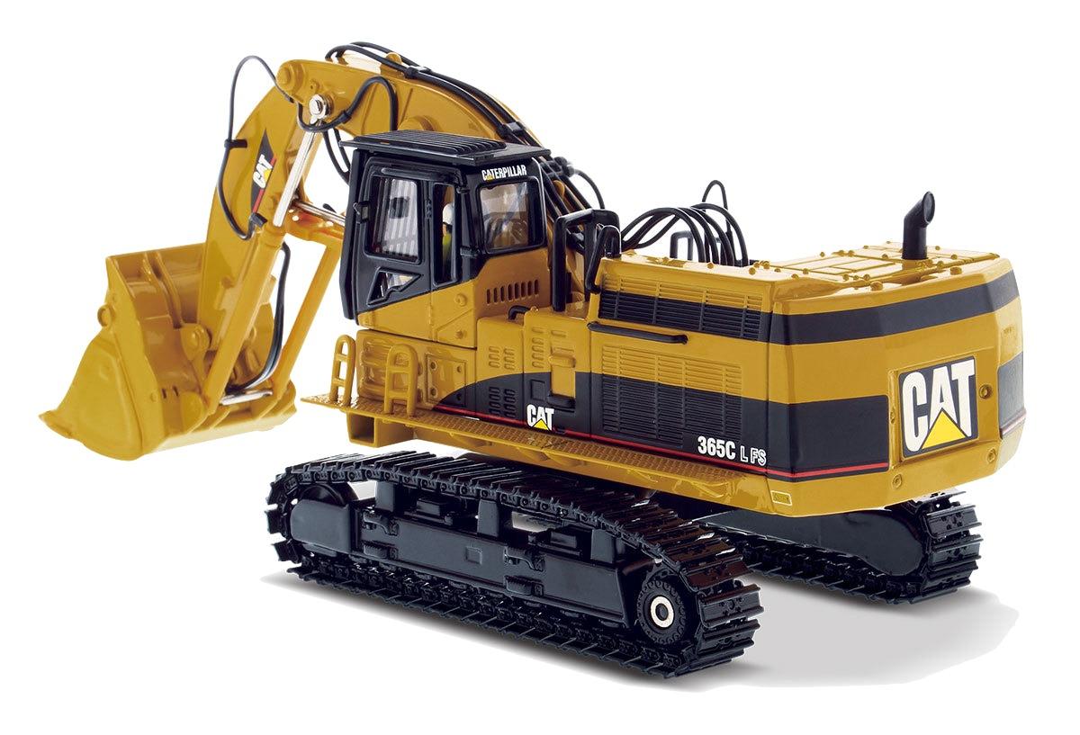
Caterpillar 365C Excavator/Material Handler/Front Shovel Factory Service & Shop Manual


Download Link

INSTANT DOWNLOAD

ADD TO CART

Complete workshop & service manual with electrical wiring diagrams for Caterpillar 365C Excavator, 365C Material Handler and 365C Front Shovel. It’s the same service manual used by dealers that guaranteed to be fully functional and intact without any missing page.

This Caterpillar 365C Excavator/Material Handler/Front Shovel service & repair manual (including maintenance, overhaul, disassembling & assembling, adjustment, tune-up, operation, inspecting, diagnostic & troubleshooting…) is divided into different sections. Each section covers a specific component or system with detailed illustrations. A table of contents is placed at the beginning of each section. Pages are easily found by category, and each page is expandable for great detail. The printer-ready PDF documents work like a charm on all kinds of devices.

MANUAL LIST:
RENR8616 – Disassembly and Assembly (365C Excavator Machine Systems)
KENR8656 – Schematic (CD700 AccuGrade Wiring for 365C & 385C Excavator Electrical System)
RENR7047 – Schematic (365C Excavators Hydraulic System (Attachment) Medium Pressure Circuit)
RENR7057 – Schematic (365C and 385C Excavators and 385C MHPU Electrical Schematic (Attachment) Medium Pressure)
RENR7062 – Schematic (365C Excavators Hydraulic System (Attachment) Boom Lowering Control Valve)
RENR7063 – Schematic (365C Excavators Hydraulic System (Attachment) Stick Lowering Control Valve)
RENR7064 – Schematic (365C Excavators Hydraulic System (Attachment) Fine Filtration)
RENR7065 – Schematic (365C Excavators Hydraulic System (Attachment) One Way Flow)
RENR7066 – Schematic (365C Excavators Hydraulic System (Attachment) Combined Function)
RENR7067 – Schematic (365C Excavators Hydraulic System (Attachment) Counterweight Removal)
RENR7068 – Schematic (365C Excavators Hydraulic System (Attachment) Smart Boom with Boom Lowering Control Valve)
RENR7215 – Schematic (365C Excavators Hydraulic System (Attachment) Smart Boom with Stick Lowering Control Valve)
RENR7216 – Schematic (365C Excavators Hydraulic System (Attachment) Reverse Fan)
RENR7303 – Specifications (365C Excavator, 365C Material Handler and 365C Front Shovel Machine System)
RENR7304 – Systems Operation (365C Excavator Hydraulic System)
RENR7305 – Testing and Adjusting (365C Excavator Hydraulic System)
RENR7306 – Schematic (365C Excavator Hydraulic System)
RENR7307 – Schematic (365C Excavator and 365C Front Shovel Electrical System)
RENR7328 – Specifications (345C, 365C and 385C Excavators Air Conditioning and Heating)
RENR7328 – Systems Operation (345C, 365C and 385C Excavators Air Conditioning and Heating)
RENR7328 – Testing and Adjusting (345C, 365C and 385C Excavators Air Conditioning and Heating)
RENR8067 – Systems Operation (365C & 385C Excavators and 365C MHPU and 385C MHPU Mobile Hydraulic Power Units Machine Electronic Control System)
RENR8067 – Testing & Adjusting (365C & 385C Excavators and 365C MHPU and 385C MHPU Mobile Hydraulic Power Units Machine Electronic Control System)
RENR8067 – Troubleshooting (365C & 385C Excavators and 365C MHPU and 385C MHPU Mobile Hydraulic Power Units Machine Electronic Control System)
RENR8615 – Disassembly and Assembly (365C Excavator Engine Supplement)

EXCERPT:
7. Install pinion (31) in swing drive housing (16) .
a. Apply Tooling (F) on the inside diameter of swing drive housing (16) .
b. Lower the temperature of pinion (31) .
c. Attach Tooling (E) and a suitable lifting device to pinion (31) .
d. Install the pinion (31) into swing drive housing (16) . Bearing (34) must be within the bore of the swing drive housing.
e. Remove Tooling (E) and the lifting device from pinion (31) . Attach the tooling and the lifting device to the swing drive housing.
f. Lift the swing drive vertically. Use a hammer and a suitable punch to align bearing (34) in the lower bore of the swing drive housing. When the bearing is properly aligned in the bore, shaft assembly (31) will drop into the proper position within the swing drive housing.

Posted on

Caterpillar 345B Excavators Factory Service & Shop Manual


INSTANT DOWNLOAD


Complete workshop & service manual with electrical wiring diagrams for Caterpillar 345B Excavators. It’s the same service manual used by dealers that guaranteed to be fully functional and intact without any missing page.

This Caterpillar 345B/345B Series II/ W345B Series II Excavators service & repair manual (including maintenance, overhaul, disassembling & assembling, adjustment, tune-up, operation, inspecting, diagnostic & troubleshooting…) is divided into different sections. Each section covers a specific component or system with detailed illustrations. A table of contents is placed at the beginning of each section. Pages are easily found by category, and each page is expandable for great detail. The printer-ready PDF documents work like a charm on all kinds of devices.

MANUAL LIST:
RENR1020 – Testing and Adjusting (320B, 322B, 325B, 330B, 345B and 345B Series II Excavators Auxiliary Hydraulic System)
RENR1043 – Disassembly and Assembly (345B, 345B Series II and W345B Series II Excavators Engine Supplement)
RENR1917 – Schematic (345B Excavator Auxiliary Flow Control Attachment Electrical System)
RENR1976 – Specifications (312B-5090B, M325B, W330B and W345B Series II Excavators Air Conditioning and Heating)
RENR1976 – Systems Operation (312B-5090B, M325B, W330B and W345B Series II Excavators Air Conditioning and Heating)
RENR1976 – Testing and Adjusting (312B-5090B, M325B, W330B and W345B Series II Excavators Air Conditioning and Heating)
RENR3125 – Schematic (Solid State Magnetic Controller for Material Handlers Electrical System)
RENR3734 – Specifications (345B Series II Excavator Machine System)
RENR3743 – Systems Operation (345B Series II Excavator Hydraulic System)
RENR3744 – Testing and Adjusting (345B Series II Excavator Hydraulic System)
RENR3756 – Schematic (345B Series II Excavator Hydraulic System)
RENR3762 – Schematic (345B Series II Excavator Electrical System)
RENR3825 – Systems Operation (320B/C, 322B/C, 325/B/C/D, 330/B/C/D, 345B, 345C, 350/L, 365B/BL, 365BL, 365C, 375L, 385C, 5080, M318, M320, M325B/C/D, W330B, W345B Series II Excavators Magnet Controller)
RENR3825 – Testing & Adjusting (320B/C, 322B/C, 325/B/C/D, 330/B/C/D, 345B, 345C, 350/L, 365B/BL, 365BL, 365C, 375L, 385C, 5080, M318, M320, M325B/C/D, W330B, W345B Series II Excavators Magnet Controller)
RENR3825 – Troubleshooting (320B/C, 322B/C, 325/B/C/D, 330/B/C/D, 345B, 345C, 350/L, 365B/BL, 365BL, 365C, 375L, 385C, 5080, M318, M320, M325B/C/D, W330B, W345B Series II Excavators Magnet Controller)
SENR1933 – Schematic (345B L Excavator Hydraulic System)
SENR1934 – Disassembly & Assembly (345B, 345B Series II and W345B Series II Excavators Machine Systems)
SENR1935 – Systems Operation (345B, 345B Series II and W345B Series II Excavators Engine and Pump Control)
SENR1935 – Testing and Adjusting Operation (345B, 345B Series II and W345B Series II Excavators Engine and Pump Control)
SENR1980 – Schematic (345B Excavator Hydraulic System – Attachment)
SENR1981 – Schematic (345B Excavator Hydraulic System – Attachment)
SENR1990 – Schematic (345B and 345B II Excavators Hydraulic System – Attachment)
RENR1020 – Systems Operation (320B, 322B, 325B, 330B, 345B and 345B Series II Excavators Auxiliary Hydraulic System).pdf

EXCERPT:
34. Install pump regulator (7) onto the cover assembly and install four socket head bolts (6) .
35. Install O-ring seal (2) on the fan pump.
36. Install flange (1) to the fan pump. Fasten the flange to the fan pump with two bolts (1a) and the washers.
37. Heat bearing (5) to 135 °C (275 °F) for thirty minutes.
38. Install bearing (5) on gear (3) .
39. Install gear (3) with bearing (5) to the pump shaft.
40. Install the lockwasher and nut (4) .


INSTANT DOWNLOAD


Posted on

Caterpillar 330B / 330B L / 330B LN Excavators Factory Service & Shop Manual


MCAT330BOPES.zip
Price: $29.99 USD

Complete workshop & service manual with electrical wiring diagrams for Caterpillar 330B / 330B L / 330B LN Excavators. It’s the same service manual used by dealers that guaranteed to be fully functional and intact without any missing page.

This Caterpillar 330B / 330B L / 330B LN Excavators service & repair manual (including maintenance, overhaul, disassembling & assembling, adjustment, tune-up, operation, inspecting, diagnostic & troubleshooting…) is divided into different sections. Each section covers a specific component or system with detailed illustrations. A table of contents is placed at the beginning of each section. Pages are easily found by category, and each page is expandable for great detail. The printer-ready PDF documents work like a charm on all kinds of devices.

MANUAL LIST:
SENR9215 – Schematic (322B, 325B, 330B Excavators Auxiliary Flow Control Attachment Electrical System)
RENR1020 – Systems Operation (320B, 322B, 325B, 330B, 345B, 345B Series II Excavators Auxiliary Hydraulic System)
RENR1020 – Testing & Adjusting (320B, 322B, 325B, 330B, 345B, 345B Series II Excavators Auxiliary Hydraulic System)
RENR1029 – Schematic (322B, 325B, 330B Forest Machines Hydraulic System – Attachment)
RENR1038 – Schematic (325B L & 330B L Excavators Hydraulic System Material Handler)
RENR1040 – Specifications (312B, 320B, 322B, 325B, 330B, 345B Excavators Air Conditioning & Heating Systems with R-134a Refrigerant)
RENR1040 – Systems Operation (312B, 320B, 322B, 325B, 330B, 345B Excavators Air Conditioning & Heating Systems with R-134a Refrigerant)
RENR1040 – Testing & Adjusting (312B, 320B, 322B, 325B, 330B, 345B Excavators Air Conditioning & Heating Systems with R-134a Refrigerant)
RENR1062 – Disassembly and Assembly (330B Excavator Material Handler Machine Systems)
RENR1064 – Schematic (330B and W330B Material Handler Electrical System)
RENR1920 – Systems Operation (322B, 325B and 330B Excavators Attachments)
RENR1920 – Testing & Adjusting (322B, 325B and 330B Excavators Attachments)
RENR1976 – Specifications (312B-5090B, M325B, W330B and W345B Series II Excavators Air Conditioning and Heating)
RENR1976 – Systems Operation (312B-5090B, M325B, W330B and W345B Series II Excavators Air Conditioning and Heating)
RENR1976 – Testing & Adjusting (312B-5090B, M325B, W330B and W345B Series II Excavators Air Conditioning and Heating)
RENR1977 – Systems Operation (325B and 330B Excavators Material Handlers)
RENR1977 – Testing & Adjusting (325B and 330B Excavators Material Handlers)
RENR1998 – Systems Operation (308B, 311B, 312B, 315B, 317B, 318B, 320B, 322B, 325B, 330B, M325B, W330B Excavators Engine and Pump Control)
RENR1998 – Testing & Adjusting (308B, 311B, 312B, 315B, 317B, 318B, 320B, 322B, 325B, 330B, M325B, W330B Excavators Engine and Pump Control)
RENR2714 – Disassembly & Assembly (330 B Excavator with Field Installed Combined/Rotate)
RENR3201 – Testing & Adjusting (330B Excavator Hydraulic System)
RENR3825 – Systems Operation (Series II, 345C, 350, 350L, 365B, 365BL, 365BL Series II, 365C, 375L, 385C, 5080, M318, M320, M325B, M325C, M325D, W330B & W345B Series II Excavators Magnet Controller)
RENR3825 – Testing & Adjusting (Series II, 345C, 350, 350L, 365B, 365BL, 365BL Series II, 365C, 375L, 385C, 5080, M318, M320, M325B, M325C, M325D, W330B & W345B Series II Excavators Magnet Controller)
RENR3825 – Troubleshooting (Series II, 345C, 350, 350L, 365B, 365BL, 365BL Series II, 365C, 375L, 385C, 5080, M318, M320, M325B, M325C, M325D, W330B & W345B Series II Excavators Magnet Controller)
SENR1668 – Schematic (330B Excavator Hydraulic System – Attachment)
SENR1676 – Schematic (330B Excavators Hydraulic System – Attachment Boom Lowering Control Valve)
SENR1677 – Schematic (330B Excavator Hydraulic System – Attachment Combined Function/Medium Pressure)
SENR1678 – Schematic (330B L Excavator Hydraulic System – Attachment)
SENR1686 – Schematic (322B, 325B, 330B Forest Machines Hydraulic System – Attachment Heel Boom)
SENR1687 – Disassembly & Assembly (330B Forest Machine – Machine Systems Supplement)
SENR1688 – Schematic (330B L Forest Swing Machine Electrical System)
SENR8968 – Disassembly & Assembly (Supplement for 330B, 330B L, & 330B LN Excavators – 3306 Engine)
SENR8969 – Specifications (330B Excavator Machine System Specifications)
SENR8972 – Schematic (330B & 330B L Excavators Hydraulic System)
SENR8973 – Disassembly & Assembly (330B, 330B L & 330B LN Excavators Machine Systems)
SENR8974 – Schematic (330B L Excavator Electrical System)
SENR8970 – Systems Operation (330B & 330B L Excavators Hydraulic System).pdf
RENR1065 – Systems Operation (320B, 322B, 325B & 330B Excavators Hydraulic System).pdf
RENR1065 – Testing and Adjusting (320B, 322B, 325B & 330B Excavators Hydraulic System).pdf
RENR2711 – System Operation (330B Excavator with Field Installed Combined/Rotate Function).pdf

EXCERPT:
(1) Lubricate the inside diameter and the outside diameter with clean grease.
(2) Rod assembly:
Diameter of rod … 109.930 ± 0.030 mm (4.3279 ± .0012 inch)
Minimum thickness for plating … 0.033 ± 0.007 mm (0.0013 ± 0.0003 inch)
(3) Bore of head … 110.73 ± 0.03 mm (4.3594 ± 0.0012 inch)
(4) Torque for nut … 13500 ± 700 N·m (9950 ± 525 lb ft)
(5) Bore of cylinder … 160.00 ± 0.10 mm (6.299 ± 0.004 inch)
(6) 087-5533 Sleeve Bearing :
Outside diameter … 106.200 ± 0.013 mm (4.1811 ± 0.0005 inch)
Inside diameter … 90.27 ± 0.02 mm (3.554 ± 0.001 inch)
Install the bearing in the bearing bore. … 10.00 ± 0.30 mm (0.394 ± 0.012 inch)
(7) 087-5548 Sleeve Bearing :

1. Thoroughly clean the outside of the main hydraulic pump prior to disassembly.
2. Remove drain plug (1), and drain the oil from the main hydraulic pump in a suitable container for disposal.
3. Fasten the main hydraulic pump to Tooling (A) as shown.
4. Remove the four socket head bolts that hold plate (2) in position. Remove plate (2) and the O-ring seal from the main pump housing.
5. Remove 12 socket head bolts (3) that hold the head group in position.