Posted on

Caterpillar TH220B/TH330B Tele-handler Factory Service & Shop Manual


Download Link

INSTANT DOWNLOAD (add to cart)


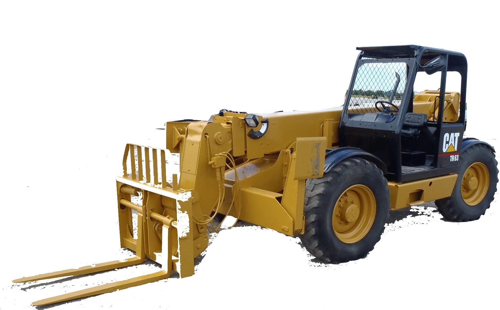
Complete workshop & service manual with electrical wiring diagrams for Caterpillar TH220B/TH330B Tele-handler. It’s the same service manual used by dealers that guaranteed to be fully functional and intact without any missing page.

These Caterpillar TH220B/TH330B Tele-handler manuals (including maintenance, overhaul, disassembling & assembling, adjustment, tune-up, operation, inspecting, diagnostic & troubleshooting…) is divided into different sections. Each section covers a specific component or system with detailed illustrations. A table of contents is placed at the beginning of each section. Pages are easily found by category, and each page is expandable for great detail. The printer-ready PDF documents work like a charm on all kinds of devices.

MANUAL LIST:
31200262 – Service Manual (TH220B, TH330B Telehandlers)
RENR5185 – Systems Operation (TH220B, TH330B, TH340B, TH350B, TH355B, TH360B, TH460B, TH560B & TH580B Telehandlers Power Train)
RENR5185 – Testing & Adjusting (TH220B, TH330B, TH340B, TH350B, TH355B, TH360B, TH460B, TH560B & TH580B Telehandlers Power Train)
RENR5189 – Systems Operation (TH220B, TH330B, TH340B, TH350B, TH355B, TH360B, TH460B, TH560B & TH580B Telehandlers Steering System)
RENR5189 – Testing & Adjusting (TH220B, TH330B, TH340B, TH350B, TH355B, TH360B, TH460B, TH560B & TH580B Telehandlers Steering System)
RENR5190 – Systems Operation (TH220B, TH330B, TH340B, TH350B, TH355B, TH360B, TH460B, TH560B & TH580B Telehandlers Braking System)
RENR5190 – Testing & Adjusting (TH220B, TH330B, TH340B, TH350B, TH355B, TH360B, TH460B, TH560B & TH580B Telehandlers Braking System)
RENR5195 – Testing & Adjusting (TH220B, TH330B, TH340B, TH350B, TH355B, TH360B, TH460B, TH560B & TH580B Telehandlers)
31200242 – Operation & Maintenance Manual (TH220B & TH330B Telehandlers).pdf
31200250 – Parts Manual (TH220B Telehandler).pdf
31200251 – Parts Manual (TH330B Telehandler).pdf
31200275 – Hydraulic Schematic (TH220B & TH330B Telehandler Hydraulic System).pdf
31200278 – Electrical Schematic (TH220B & TH330B Telehandler Electrical System).pdf
31200285 – Manual de Operación y Mantenimiento (Manipuladores Telescópicos TH220B y TH330B).pdf
RENR5195 – Troubleshooting (TH220B, TH330B, TH340B, TH350B, TH355B, TH360B, TH460B, TH560B & TH580B Telehandlers)
31200346 – Manual de Operação e Manutenção (Manipuladores Telescópicos TH220B e TH330B).pdf
RENR5196 – Systems Operation (TH220B, TH330B, TH340B, TH350B, TH355B, TH360B, TH460B, TH560B & TH580B Telehandlers Longitudinal Stability Indicator System)
RENR5196 – Testing & Adjusting (TH220B, TH330B, TH340B, TH350B, TH355B, TH360B, TH460B, TH560B & TH580B Telehandlers Longitudinal Stability Indicator System)
RENR6704 – Systems Operation (TH220B, TH330B, TH340B, TH350B, TH355B, TH360B, TH460B, TH560B & TH580B Telehandlers Machine Monitor System)
RENR6704 – Testing & Adjusting (TH220B, TH330B, TH340B, TH350B, TH355B, TH360B, TH460B, TH560B & TH580B Telehandlers Machine Monitor System)

EXCERPT:
Thumb Slider
The thumb slider (6) can be configured in one of two modes.
The thumb slider sensor is configured in the North American Construction configuration. Then, the thumb slider sensor is configured for the coupler tilt. The telescope in and the telescope out is configured for the side-to-side movement of the joystick.
The thumb slider sensor is configured in the Bucket mode configuration. The thumb slider sensor is configured for the telescope in and the telescope out.
Then, the side to side motion of the joystick is for the coupler tilt.
Boom Critical Angle Switch

Posted on

Caterpillar TH103 Tele-handler Factory Service & Shop Manual


Download Link

INSTANT DOWNLOAD (add to cart)


Complete workshop & service manual with electrical wiring diagrams for Caterpillar TH103 Tele-handler. It’s the same service manual used by dealers that guaranteed to be fully functional and intact without any missing page.

These Caterpillar TH103 Tele-handler manuals (including maintenance, overhaul, disassembling & assembling, adjustment, tune-up, operation, inspecting, diagnostic & troubleshooting…) is divided into different sections. Each section covers a specific component or system with detailed illustrations. A table of contents is placed at the beginning of each section. Pages are easily found by category, and each page is expandable for great detail. The printer-ready PDF documents work like a charm on all kinds of devices.

MANUAL LIST:
RENR3405 – Schematic (TH103 Electrical System)
RENR3413 – Schematic (TH103 Telehandler Electrical System)
RENR3416 – Schematic (TH103 Telehandler Electrical System)
RENR3445 – Schematic (TH103 Telehandler Hydraulic System)
RENR3460 – Systems Operation (TH103, TH62, TH63, TH82 & TH83 Telehandlers Longitudinal Stability Indicator)
RENR3460 – Testing & Adjusting (TH103, TH62, TH63, TH82 & TH83 Telehandlers Longitudinal Stability Indicator)
RENR3463 – Specifications (TH103 Telehandler Steering & Hydraulic System)
RENR3475 – Systems Operation (TH103 Telehandler Steering System)
RENR3475 – Testing & Adjusting (TH103 Telehandler Steering System)
RENR3476 – Systems Operation (TH103 Telehandler Hydraulic System)
RENR3476 – Testing & Adjusting (TH103 Telehandler Hydraulic System)
RENR3478 – Schematic (TH103 Telehandler Hydraulic System)
RENR3491 – Systems Operation (TH103 Telehandler Hydraulic System)
RENR3491 – Testing & Adjusting (TH103 Telehandler Hydraulic System)
RENR3492 – Schematic (TH103 Telehandler Hydraulic System)
RENR5105 – Specifications (TH103 Telehandler Braking System)
RENR5105 – Systems Operation (TH103 Telehandler Braking System)
RENR5105 – Testing & Adjusting (TH103 Telehandler Braking System)
SENR1234 – Specifications (TH103 Telehandler Power Train)
SENR1234 – Systems Operation (TH103 Telehandler Power Train)
SENR1234 – Testing & Adjusting (TH103 Telehandler Power Train)
SENR1235 – Disassembly & Assembly (TH103 Telehandler Power Train)
SENR1236 – Specifications (TH103 Telehandler Steering & Hydraulic System)
SENR1239 – Systems Operation (TH103 Telehandler Hydraulic System)
SENR1239 – Testing & Adjusting (TH103 Telehandler Hydraulic System)
SENR1241 – Disassembly & Assembly (TH103 Machine Systems Disassembly & Assembly)
SENR1242 – Disassembly & Assembly (TH103 Telehandler Transmission)
SENR1244 – Specifications (TH103 Telehandler Transmission)
SENR1237 – Systems Operation (TH103 Telehandler Steering System).pdf
SENR1237 – Testing & Adjusting (TH103 Telehandler Steering System).pdf
SENR1238 – Systems Operation (TH103 Telehandler Brake System).pdf
SENR1238 – Testing & Adjusting (TH103 Telehandler Brake System).pdf
SENR1240 – Schematic (TH103 Telehandler Hydraulic System).pdf
SENR1244 – Systems Operation (TH103 Telehandler Transmission).pdf
SENR1244 – Testing & Adjusting (TH103 Telehandler Transmission).pdf

EXCERPT:
7. Install spacer (8) and spring assembly (6) into the drum assembly for the forward high clutch (2) .
Note: The large diameter of the first belleville washer of the spring assembly goes next to the spacer. Then alternate the following four washers of the spring assembly.
8. Use Tool (B) in order to compress spring assembly (6) . Then use Tool (A) to install snap ring (7) .

Posted on

Caterpillar TH62, TH63, TH82, TH83 Tele-handler Factory Service & Shop Manual


Download Link

INSTANT DOWNLOAD (add to cart)


Complete workshop & service manual with electrical wiring diagrams for Caterpillar TH62, TH63, TH82, TH83 Tele-handler. It’s the same service manual used by dealers that guaranteed to be fully functional and intact without any missing page.

These Caterpillar Caterpillar Caterpillar TH62, TH63, TH82, TH83 Tele-handler manuals (including maintenance, overhaul, disassembling & assembling, adjustment, tune-up, operation, inspecting, diagnostic & troubleshooting…) is divided into different sections. Each section covers a specific component or system with detailed illustrations. A table of contents is placed at the beginning of each section. Pages are easily found by category, and each page is expandable for great detail. The printer-ready PDF documents work like a charm on all kinds of devices.

MANUAL LIST:
TEJB9602 – Product Bulletin (Work Tools for Cat Telehandlers).pdf
RENR1377 – Systems Operation (Electric Protection System Energize-To-Run for Generator Set, Industrial & Marine Diesel Engines)
RENR1377 – Testing & Adjusting (Electric Protection System Energize-To-Run for Generator Set, Industrial & Marine Diesel Engines)
RENR3404 – Schematic (TH62, TH63, TH82 & TH83 Electrical System)
RENR3407 – Schematic (TH62, TH63, TH82 & TH83 Telehandler Electrical System)
RENR3415 – Schematic (TH62, TH63, TH82 & TH83 Telehandler Electrical System)
RENR3443 – Schematic (TH62, TH63, TH82 & TH83 Telehandler Hydraulic System for Type 1, Type 3 or Type A Control Arrangements)
RENR3444 – Schematic (TH62, TH63, TH82 & TH83 Telehandler Hydraulic System for Type 2, Type 4 or Type B Control Arrangements)
RENR3453 – Disassembly & Assembly (TH62, TH63, TH82, TH83 & TH103 Telehandlers Engine Supplement)
RENR3455 – Systems Operation (TH62, TH63, TH82 & TH83 Telehandlers Steering System)
RENR3455 – Testing & Adjusting (TH62, TH63, TH82 & TH83 Telehandlers Steering System)
RENR3458 – Schematic (TH62, TH63, TH82 & TH83 Telehandler Hydraulic System for Type ‘A’ Control Arrangement)
RENR3462 – Specifications (TH62, TH63, TH82 & TH83 Telehandlers Steering and Hydraulic System)
RENR3473 – Schematic (TH62, TH63, TH82 & TH83 Telehandler Hydraulic System for Type ‘B’ Control Arrangemen)
RENR5106 – Specifications (TH62, TH63, TH82 & TH83 Telehandlers Braking System)
RENR5106 – Systems Operation (TH62, TH63, TH82 & TH83 Telehandlers Braking System)
RENR5106 – Testing & Adjusting (TH62, TH63, TH82 & TH83 Telehandlers Braking System)
SEGV3008 – Systems Operation (Fundamentals Electrical System for All Caterpillar Products)
SENR3130 – Torque Specifications
SENR3685 – Disassembly & Assembly (Alternator – Bosch K1_N1)
SENR3685 – Specifications (Alternator – Bosch K1_N1)
SENR3685 – Systems Operation (Alternator – Bosch K1_N1)
SENR3685 – Testing & Adjusting (Alternator – Bosch K1_N1)
SENR3685 – Troubleshooting (Alternator – Bosch K1_N1)
SENR3828 – Disassembly & Assembly (RA1.2, R1.4, R2.0, R2.2, R2.5, R2.7, R3.0, R4.5 and R5.5 Series Reduction Starting Motors)
SENR3828 – Specifications (RA1.2, R1.4, R2.0, R2.2, R2.5, R2.7, R3.0, R4.5 and R5.5 Series Reduction Starting Motors)
SENR3828 – Systems Operation (RA1.2, R1.4, R2.0, R2.2, R2.5, R2.7, R3.0, R4.5 and R5.5 Series Reduction Starting Motors)
SENR3828 – Testing & Adjusting (RA1.2, R1.4, R2.0, R2.2, R2.5, R2.7, R3.0, R4.5 and R5.5 Series Reduction Starting Motors)
SENR3981 – Schematic – Fluid Power & Electrical Graphic Symbols
SENR5841 – Disassembly & Assembly (G3B, K3A & L3A Denso Alternators)
SENR5841 – Specifications (G3B, K3A & L3A Denso Alternators)
SENR5841 – Systems Operation (G3B, K3A & L3A Denso Alternators)
SENR5841 – Testing & Adjusting (G3B, K3A & L3A Denso Alternators)
SENR5844 – Systems Operation (TH62, TH63, TH82 & TH83 Telehandlers Braking System)
SENR5844 – Testing & Adjusting (TH62, TH63, TH82 & TH83 Telehandlers Braking System)
SENR5847 – Schematic (TH62, TH63, TH82, TH83 & TH103 Telehandler Electrical System)
SENR5851 – Disassembly & Assembly (TH62, TH63, TH82 & TH83 Telehandlers Engine Supplement)
SENR5857 – Specifications (TH62, TH63, TH82 & TH83 Telehandlers Steering & Hydraulic)
UENR3262 – Disassembly & Assembly – Seal Installation
RENR3436 – Disassembly & Assembly (TH62, TH63, TH82, TH83 & TH103 Telehandlers Power Train).pdf
RENR3437 – Disassembly & Assembly (TH62, TH63, TH82, TH83 & TH103 Telehandlers Machine Systems).pdf
SEBF9050 – Applied Failure Analysis – Engine Valve Failure Modes{1100, 1105}.pdf
SEBU6875 – Owner’s Manual (Caterpillar Driver Information Display).pdf
SENR2995 – Product Safety.pdf
SENR3130 – Specifications (Torque Specifications for All Caterpillar Products).pdf
SENR5840 – Disassembly & Assembly (TH62, TH63, TH82 & TH83 Telehandlers Power Train).pdf
SENR5845 – Schematic (TH62, TH63, TH82 & TH83 Telehandlers Hydraulic System).pdf
SENR5846 – Disassembly and Assembly (TH62, TH63 TH82 & TH83 Telehandlers Machine Systems).pdf…

EXCERPT:
Note: Be very careful in the performance of this step. Ensure that the soft drift is in contact with the end of splined hub (4). Do not attempt to apply pressure on retaining washer (2). The outside diameter of the retaining washer is larger than the inside diameter of the bearing (not shown).
3. Use a soft drift and a hammer in order to drive the splined hub out of the bearing (5) (not shown).

Engine and Transmission
Remove Engine and Transmission.
Start By:
a. Remove battery. b. Remove radiator.
1. Remove four nuts (1), bolts (2) and washers (3) and remove hood and hood support (4).
2. Disconnect electrical cables (5) from alternator.
3. Remove three nuts (6), washers (7) and disconnect exhaust pipe (8).
4. Disconnect electrical cables (9) from starter motor solenoid. Remove nut (10) and disconnect earth cable (11).
5. Disconnect air intake hose (12) from beneath air cleaner assembly.
6. Remove bolt (13), washer (14) and clip (15) and detach battery cables from transmission.

Bank Valve – Assemble
Assembly Procedure
Note: Cleanliness is an important factor. Before assembly, all parts should be thoroughly cleaned in cleaning fluid. Allow the parts to air dry. Wiping cloths or rags should not be used to dry parts. Lint may be deposited on the parts which may cause later trouble. Inspect all parts. If any parts are worn or damaged, use new parts for replacement. All disassembly and all assembly procedures must be performed on a clean work surface and in a clean hydraulic area. Keep cleaned parts covered and protected at all times.
Note: O-rings, gaskets, and seals should always be replaced. A used O-ring may not have the same sealing properties as a new O-ring. Use 1U-6396 O-Ring Assembly Compound during the assembly procedure.

Posted on

Caterpillar C175 Engines Factory Service & Shop Manual


Download Link

INSTANT DOWNLOAD (add to cart)


Complete workshop & service manual with electrical wiring diagrams for Caterpillar C175-16 Generator Set . It’s the same service manual used by dealers that guaranteed to be fully functional and intact without any missing page.

This Caterpillar C175-16 Generator Set service & repair manual (including maintenance, overhaul, disassembling & assembling, adjustment, tune-up, operation, inspecting, diagnostic & troubleshooting…) is divided into different sections. Each section covers a specific component or system with detailed illustrations. A table of contents is placed at the beginning of each section. Pages are easily found by category, and each page is expandable for great detail. The printer-ready PDF documents work like a charm on all kinds of devices.

MANUAL LIST:
SEBP4467 – Parts Manual (Preliminary Information) (C175-16 Generator Set).pdf
KENR6862 – Specifications (C175-16 Marine Engine)
KENR6863 – Systems Operation (C175-16 Locomotive Engine)
KENR6863 – Testing & Adjusting (C175-16 Locomotive Engine)
KENR6864 – Troubleshooting (C175-16 Locomotive Engine)
KENR8116 – Disassembly & Assembly (C175-16 Locomotive Engine)
UENR1791 – Schematic (C175-16 Locomotive Engine Electrical System)


EXCERPT:
1. switch to the OFF position.
Turn the fuel supply valve to the OFF position.
NOTICE
Care must be taken to ensure that fluids are contained during performance of inspection, maintenance, testing, adjusting, and repair of the product. Be prepared to collect the fluid with suitable containers before opening any compartment or disassembling any component containing fluids.
Refer to Special Publication, NENG2500, “Dealer Service Tool Catalog” for tools and supplies suitable to collect and contain fluids on Cat products.
Dispose of all fluids according to local regulations and mandates.
2. Drain the oil from the engine into a suitable container for storage or for disposal. Refer to Operation and Maintenance Manual, “Engine Oil and Filter – Change”.

Posted on

Caterpillar G3516B & G3520B Engines Factory Service & Shop Manual


Download Link

INSTANT DOWNLOAD (add to cart)


Complete workshop & service manual with electrical wiring diagrams for G3516B & G3520B Generator Set Engines. It’s the same service manual used by dealers that guaranteed to be fully functional and intact without any missing page.

This G3516B & G3520B Generator Set Engines service & repair manual (including maintenance, overhaul, disassembling & assembling, adjustment, tune-up, operation, inspecting, diagnostic & troubleshooting…) is divided into different sections. Each section covers a specific component or system with detailed illustrations. A table of contents is placed at the beginning of each section. Pages are easily found by category, and each page is expandable for great detail. The printer-ready PDF documents work like a charm on all kinds of devices.

MANUAL LIST:
SEBP3376 – Parts Manual (G3516B Generator Set).pdf
RENR2267 – Specifications (G3500B Engines)
RENR2268 – Systems Operation (G3500B Engines)
RENR2268 – Testing & Adjusting (G3500B Engines)
RENR2269 – Disassembly & Assembly (G3516B & G3520B Generator Set Engines)
RENR2270 – Troubleshooting (G3516B Engines)
RENR2460 – Schematic (G3516B Engine Electrical System)
RENR5946 – Schematic (G3516B Generator Set Electrical System)
RENR8101 – Schematic (G3516B Generator Set Electrical System (for SN ZBB1-UP, CSC290-UP, ZBC1-UP, CME284-UP & L6J1-UP))

EXCERPT:
Place clean engine oil on the bearing and install shaft (6) 4. in front adapter assembly (9).
Install retaining washer (10) and the bolts.
Note: Later models have two retaining washers.