Posted on

Caterpillar C7.1 Engines Factory Service & Shop Manual


Download Link

INSTANT DOWNLOAD (add to cart)


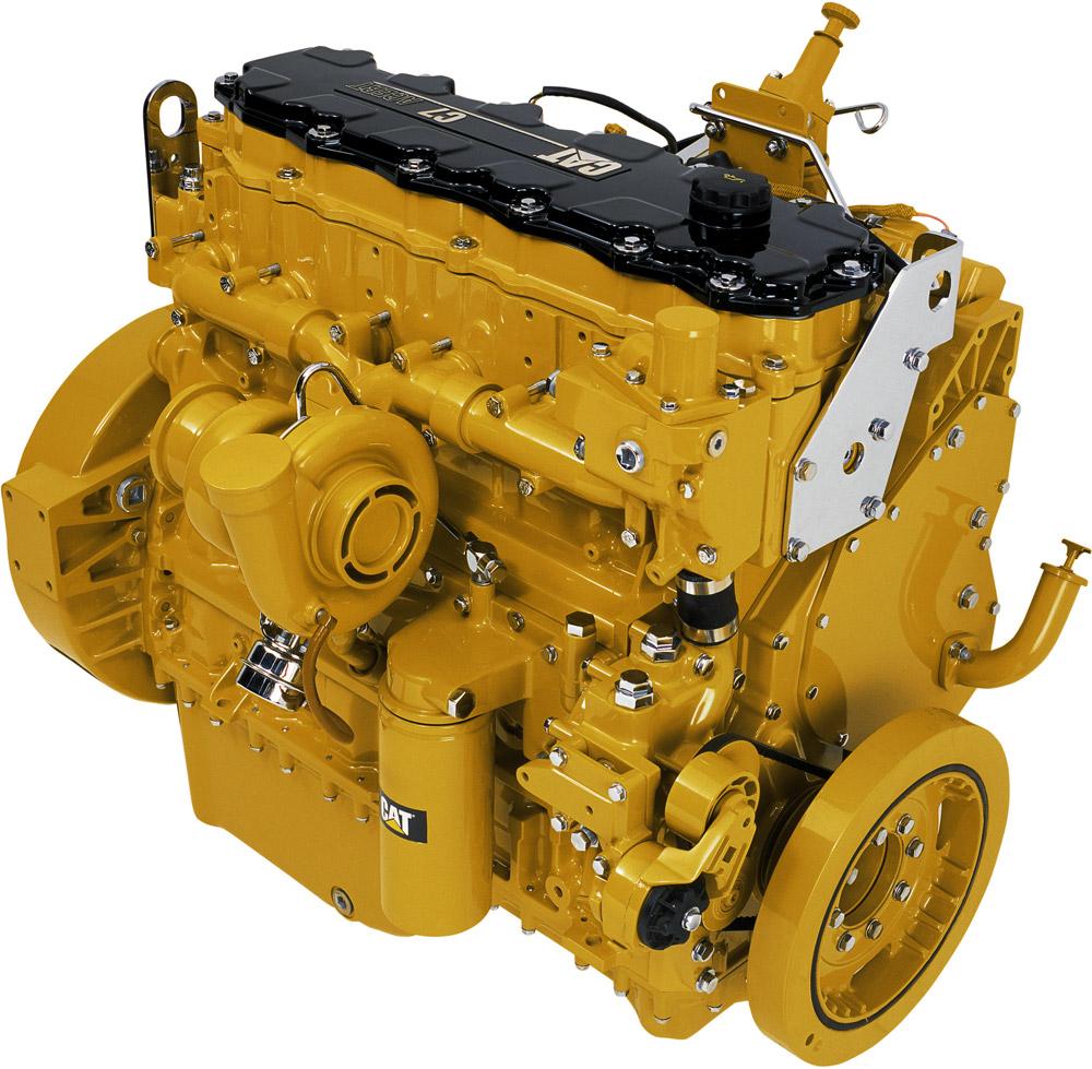
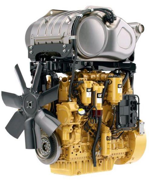
Complete workshop & service manual with electrical wiring diagrams for Caterpillar C7.1 Engines. It’s the same service manual used by dealers that guaranteed to be fully functional and intact without any missing page.

This Caterpillar C7.1 Engines service & repair manual (including maintenance, overhaul, disassembling & assembling, adjustment, tune-up, operation, inspecting, diagnostic & troubleshooting…) is divided into different sections. Each section covers a specific component or system with detailed illustrations. A table of contents is placed at the beginning of each section. Pages are easily found by category, and each page is expandable for great detail. The printer-ready PDF documents work like a charm on all kinds of devices.

MANUAL LIST:
KENR9226 – Troubleshooting (C7.1 Engines for Caterpillar Built Machines)
KENR8881 – Disassembly & Assembly (C7.1 Engines for Caterpillar Built Machines)
KENR9128 – Troubleshooting (C7.1 Engines for Caterpillar Built Machines)
KENR9240 – Specifications (C7.1 Engines for Caterpillar Built Machines)
KENR9241 – Systems Operation (C7.1 Engines for Caterpillar Built Machines)
KENR9241 – Testing & Adjusting (C7.1 Engines for Caterpillar Built Machines)
KENR9511 – Schematic (Marine Multi-Station Control System II Electrical System – Typical Dual Engine Installation)
RENR1377 – Systems Operation (Electric Protection System Energize-To-Run for Generator Set, Industrial & Marine Diesel Engines)
RENR1377 – Testing & Adjusting (Electric Protection System Energize-To-Run for Generator Set, Industrial & Marine Diesel Engines)
RENR7651 – Systems Operation (Marine Multi-Station Control System)
RENR7651 – Testing & Adjusting (Marine Multi-Station Control System)
RENR7651 – Troubleshooting (Marine Multi-Station Control System)
RENR7893 – Schematic (Marine Multi-Station Control System Electrical System – Typical Single Engine Installation)
RENR7929 – Schematic (Marine Multi-Station Control System Electrical System – Typical Dual Engine Installation)
SENR3130 – Torque Specifications
UENR3262 – Disassembly & Assembly – Seal Installation
LEBW4976 – Application & Installation Guide (Diesel Fuel & Diesel Fuel Systems).pdf
REHS1413 – Special Instruction – Installation of Cat Messenger for On-highway Engines.pdf
RENR1282 – Electronic PTO Installation & Application Guide (On-Highway Engines).pdf
SEBF9050 – Applied Failure Analysis – Engine Valve Failure Modes(1100, 1105).pdf
SENR2995 – Product Safety.pdf
SENR3130 – Specifications – Torque Specifications.pdf
SENR3130 – Specifications (Torque Specifications for All Caterpillar Products).pdf
SERT4052 – Service Training (Acert Technology for On-Highwayheavy Duty Engines).pdf

EXCERPT:
1. Release the pressure from the air system. Refer to the Original Equipment Manufactures (OEM) for the correct procedure.
2. Drain the coolant from the cooling system into a suitable container for storage or for disposal. Refer to Operation and Maintenance Manual, “Cooling System Coolant – Change” for the correct draining procedure.
If the engine is equipped with a hydraulic pump on the rear of the air compressor, remove the hydraulic pump. Refer to the OEM for the correct procedure.
3. Use Tooling (A) in order to rotate the crankshaft so that number one piston is at the top center position on the compression stroke. Refer to Systems Operation, Testing and Adjusting, “Finding Top Center Position for No.1 Piston” for the correct procedure.
4. Note: The air compressor must be timed with the engine in order to minimize engine vibration.

Posted on

Caterpillar C7 Engines Workshop Repair & Service Manual


Download Link

INSTANT DOWNLOAD (add to cart)


Complete digital official shop manual contains service, maintenance, and troubleshooting information for the Caterpillar C7 Engines. Diagnostic and repair procedures are covered in great detail to repair, maintain, rebuild, refurbish or restore your engine like a professional mechanic in local service/repair workshop. This cost-effective quality manual is 100% complete and intact as should be without any missing pages. It is the same factory shop manual used by dealers that guaranteed to be fully functional to save your precious time.

This manual for Caterpillar C7 Engines is divided into different sections. Each section covers a specific component or system and, in addition to the standard service procedures, includes disassembling, inspecting, and assembling instructions. A table of contents is placed at the beginning of each section. Pages are easily found by category, and each page is expandable for great detail. It is in the cross-platform PDF document format so that it works like a charm on all kinds of devices. You do not need to be skilled with a computer to use the manual.

MANUAL LIST:
ERENR9218 – Disassembly & Assembly (C7 Engines for Caterpillar Built Machines)
SENR9938 – Specifications (C7 Engines for Caterpillar Built Machines)
SENR9939 – Systems Operation (C7 Engines for Caterpillar Built Machines)
SENR9939 – Testing & Adjusting (C7 Engines for Caterpillar Built Machines)
RENR7458 – Disassembly & Assembly (C7 On-Highway Engine).pdf
RENR7571 – Specifications (C7 On-highway Engine).pdf
RENR7572 – Systems Operation, Testing & Adjusting (C7 On-highway Engine).pdf
RENR7691 – Schematic (C7 On-Highway Engine Electrical System).pdf
RENR7872 – Schematic (C7 On-Highway Engine Electrical System).pdf
RENR7913 – Schematic (C7 On-Highway Engine Electrical System).pdf
SEBP4436 – Parts Manual (C7 Industrial Engine).pdf
SEBU6875 – Owner’s Manual (Caterpillar Driver Information Display).pdf
SEBU7766 – Operation & Maintenance Manual (C7 On-highway Engine).pdf
SEBU7926 – Operation & Maintenance Manual (C7 Urban Transit Bus Engines).pdf
SEBU8089 – Operation & Maintenance Manual (C7 Industrial Engine).pdf

EXCERPT:
Component Description
Hydraulic Electronic Unit Injector
The HEUI fuel system utilizes a hydraulically actuated electronically controlled unit injector (5).
All fuel systems for diesel engines use a plunger and barrel in order to pump fuel under high pressure into the combustion chamber. This fuel is pumped into the combustion chamber in precise amounts in order to control engine performance. The HEUI uses engine oil under high pressure in order to power the plunger. All other fuel systems use a fuel injection pump camshaft lobe in order to power the plunger.
Because the HEUI is much different, a technician must use different troubleshooting methods.
The HEUI uses engine lubrication oil that is pressurized from 6 MPa (870 psi) to 28 MPa (4050 psi) in order to pump fuel from the injector.
The HEUI operates in the same way as a hydraulic cylinder in order to multiply the force of the high pressure oil. By multiplying the force of the high pressure oil, the HEUI can produce injection pressures that are very high. This multiplication of pressure is achieved by applying the force of the high pressure oil to a piston. The piston is larger than the plunger by approximately six times. The piston that is powered by engine lubrication oil under high pressure pushes on the plunger. This engine lubrication oil under high pressure is called the actuation pressure of the oil. The actuation pressure of the oil generates the injection pressure that is delivered by the unit injector. Injection pressure is greater than actuation pressure of the oil by approximately six times.
Low actuation pressure of the oil results in low injection pressure of the fuel. During conditions of low speed such as idle and start, low injection pressure is utilized.
High actuation pressure of the oil results in high injection pressure of the fuel. During conditions of high speed such as high idle and acceleration, high injection pressure is utilized.

Water Temperature Regulator – Remove and Install
Removal Procedure
NOTICE
Keep all parts clean from contaminants. Contaminants may cause rapid wear and shortened component life.
NOTICE
Care must be taken to ensure that fluids are contained during performance of inspection, maintenance, testing, adjusting and repair of the product. Be prepared to collect the fluid with suitable containers before opening any compartment or disassembling any component containing fluids.
Refer to Special Publication, NENG2500, “Caterpillar Tools and Shop Products Guide” for tools and supplies suitable to collect and contain fluids on Caterpillar products.
Dispose of all fluids according to local regulations and mandates.
1. Drain the coolant from the cooling system into a suitable container for storage or disposal. Refer to Operation and Maintenance Manual, “Cooling System Coolant – Change”.
Illustration 54 g01152619
2. Remove bolts (1), pipe (2), and the gasket from water temperature regulator housing (3).
3. Remove the water temperature regulators.
Installation Procedure
NOTICE
Keep all parts clean from contaminants.
Contaminants may cause rapid wear and shortened component life.

Posted on

Caterpillar C4.4 Engines Factory Service & Shop Manual


Download Link

INSTANT DOWNLOAD (add to cart)


Complete workshop & service manual with electrical wiring diagrams for Caterpillar C4.4 Engines. It’s the same service manual used by dealers that guaranteed to be fully functional and intact without any missing page.

This Caterpillar C4.4 Engines Engines service & repair manual (including maintenance, overhaul, disassembling & assembling, adjustment, tune-up, operation, inspecting, diagnostic & troubleshooting…) is divided into different sections. Each section covers a specific component or system with detailed illustrations. A table of contents is placed at the beginning of each section. Pages are easily found by category, and each page is expandable for great detail. The printer-ready PDF documents work like a charm on all kinds of devices.

ENGINE – GENERATOR SET
Model Prefix
C4.4 GENERATOR SET D4B
C4.4 GENERATOR SET D4D
C4.4 GENERATOR SET GLD
C4.4 GENERATOR SET GLE
C4.4 GENERATOR SET GTH
C4.4 GENERATOR SET L4R
C4.4 GENERATOR SET L4T
C4.4 GENERATOR SET LC4
C4.4 GENERATOR SET LC5
C4.4 GENERATOR SET MZT
C4.4 GENERATOR SET N4D
C4.4 GENERATOR SET N4E
C4.4 GENERATOR SET N4R
C4.4 GENERATOR SET N4X
C4.4 GENERATOR SET NCD
C4.4 GENERATOR SET NCE
C4.4 GENERATOR SET XYC
C4.4 GENERATOR SET XYD
C4.4DE110E GENERATOR SET ECL
C4.4DE55E2 GENERATOR SET EC7
C4.4DE55E2 GENERATOR SET GT6
C4.4DE65E3 GENERATOR SET EC8
C4.4DE65E3 GENERATOR SET GT8
C4.4DE88E0 GENERATOR SET EC9
C4.4DE88E0 GENERATOR SET GT9
C4.4DE88E3 GENERATOR SET ECK
C4.4DE88E3 GENERATOR SET GTD
C4.4XQ100 GENERATOR SET XRB
C4.4XQ80 GENERATOR SET XRA

ENGINE – INDUSTRIAL
Model Prefix
C4.4 INDUSTRIAL ENGINE 440
C4.4 INDUSTRIAL ENGINE 444
C4.4 INDUSTRIAL ENGINE 446
C4.4 INDUSTRIAL ENGINE 448
C4.4 INDUSTRIAL ENGINE JKT
C4.4 INDUSTRIAL ENGINE W23
C4.4 REMAN ENGINE P4X

ENGINE – MACHINE
Model Prefix
C4.2 ENGINE – MACHINE JKH
C4.4 ENGINE – MACHINE 444
C4.4 ENGINE – MACHINE 446
C4.4 ENGINE – MACHINE 448
C4.4 ENGINE – MACHINE C4E
C4.4 ENGINE – MACHINE C4Z
C4.4 ENGINE – MACHINE C7N
C4.4 ENGINE – MACHINE CRS
C4.4 ENGINE – MACHINE JKT
C4.4 ENGINE – MACHINE PM5
C4.4 ENGINE – MACHINE W23
C4.4 ENGINE – MACHINE W7N

MARINE PRODUCTS
Model Prefix
C4.4 GENERATOR SET L1K
C4.4 GENERATOR SET MMC
C4.4 GENERATOR SET NRP
C4.4 GENERATOR SET S1M

Model Prefix
C6.4 ENGINE – MACHINE GDC
C6.4 ENGINE – MACHINE MAE

ENGINE – GENERATOR SET
Model Prefix
C6.6 GENERATOR SET LC6
C6.6 GENERATOR SET MRW
C6.6 GENERATOR SET N6D
C6.6 GENERATOR SET SDA
C6.6DE150E GENERATOR SET ECR
C6.6DE150E GENERATOR SET GTM

ENGINE – INDUSTRIAL
Model Prefix
C6.6 INDUSTRIAL ENGINE 666
C6.6 INDUSTRIAL ENGINE 667
C6.6 INDUSTRIAL ENGINE PH0
C6.6 REMAN ENGINE 661

ENGINE – MACHINE
Model Prefix
C6.6 ENGINE – MACHINE C6E
C6.6 ENGINE – MACHINE C8N
C6.6 ENGINE – MACHINE G9G

MARINE PRODUCTS
Model Prefix
C6.6 GENERATOR SET C6T

FILELIST:
KENR6248 – Specifications (C4.4 (Mech) Industrial Engine)
KENR6249 – Disassembly & Assembly (C4.4 (Mech) Industrial Engine & Generator Sets)
KENR6900 – Systems Operation (C4.4 (Mech) Industrial Engine)
KENR6900 – Troubleshooting (C4.4 (Mech) Industrial Engine)
KENR9118 – Specifications (C4.4 Industrial Engine)
KENR9119 – Systems Operation (C4.4 Industrial Engine)
KENR9119 – Testing & Adjusting (C4.4 Industrial Engine)
KENR9120 – Disassembly & Assembly (C4.4 Industrial Engine)
KENR9122 – Schematic (C4.4 Industrial Engine Electrical System)
KENR9205 – Disassembly & Assembly (C4.4 Generator Sets)
KENR9206 – Troubleshooting (C4.4 Engines for Caterpillar Built Machines)
KENR9562 – Schematic (C4.4 XQ45 & XQ60 Generator Set Electrical System)
M0074066 – Troubleshooting (C4.4 & C6.6 Engines)
SERV1837 – Technical Presentation (C4.2, C4.4, C6.4, C6.6 (Acert) Engines with Common Rail Fuel System).pdf
SEBU8606 – Operation & Maintenance Manual (C4.4 Industrial Engine).pdf

EXCERPT:
Sequence for tightening accessory drive
Inspect the bore in front housing (3) for damage. If necessary, replace the front housing. Refer to Disassembly and Assembly, “Housing (Front) – Remove” and Disassembly and Assembly, “Housing (Front) – Install”.
1. Lightly lubricate a new O-ring seal (5) (not shown) with Tooling (C). Install the O-ring seal (not shown) into the groove in accessory drive housing (4) .
2. Lightly lubricate all bearings, and all gears with clean engine lubricating oil. Install the assembly of the accessory drive to the front housing. Ensure that the flange on the accessory drive housing is flush with the front housing.
3. Apply Tooling (D) to allen head screws (1) and allen (2) in the sequence that is shown in Illustration 2.
4. head screw (2) .
5. Install allen head screws (1) and allen head screw (2) to accessory drive housing (4) .
6. Tighten allen head screws (1) to a torque of 22 N·m (16 lb ft).
Tighten allen head screw (2) to a torque of 44 N·m (32 lb ft). Tighten allen head screws (1) and

Posted on

Caterpillar 320B, 320B L, 320B LL, 320B LN, 320B N & 320B S Excavators Factory Service & Shop Manual


Download Link

INSTANT DOWNLOAD (add to cart)


Complete workshop & service manual with electrical wiring diagrams for Caterpillar 320B, 320B L, 320B LL, 320B LN, 320B N & 320B S Excavators. It’s the same service manual used by dealers that guaranteed to be fully functional and intact without any missing page.

This Caterpillar 320B, 320B L, 320B LL, 320B LN, 320B N & 320B S Excavators service & repair manual (including maintenance, overhaul, disassembling & assembling, adjustment, tune-up, operation, inspecting, diagnostic & troubleshooting…) is divided into different sections. Each section covers a specific component or system with detailed illustrations. A table of contents is placed at the beginning of each section. Pages are easily found by category, and each page is expandable for great detail. The printer-ready PDF documents work like a charm on all kinds of devices.

MANUAL LIST:
RENR1000 – Schematic (320B & 320B L Excavators Hydraulic System (Attachment) Third Pedal Straight Travel)
RENR1001 – Schematic (320B Excavators Hydraulic System – Attachment One Way_One PU)
RENR1002 – Schematic (320B & 320B L Excavators Hydraulic System Two Pump Flow (Attachment) with 3rd Pedal Straight Travel)
RENR1003 – Schematic (320B & 320B L Excavators Hydraulic System Double Action 1 Pump (Attachment) with 3rd Pedal Straight Travel)
RENR1004 – Schematic (320B & 320B L Excavators Hydraulic System Single Flow Control (Attachment))
RENR1005 – Schematic (320B & 320B L Excavators Hydraulic System Common Flow Cont.)
RENR1006 – Schematic (320B Excavator Hydraulic System – Attachment – Common Piping_Third Pedal (Interactive) 118-4192)
RENR1992 – Systems Operation (320B, 322B, 325B & 330B Excavators Attachment Hydraulic Systems)
RENR1992 – Testing & Adjusting (320B, 322B, 325B & 330B Excavators Attachment Hydraulic Systems)
RENR2728 – Disassembly & Assembly (320B Excavator with Field Installed Combined/Rotate Function)
RENR3277 – Testing & Adjusting (320B, 322B & 325B Excavators Long Reach Front Attachment Hydraulic System)
RENR3726 – Schematic (320B Excavator Hydraulic System)
SENR5556 – Disassembly & Assembly (Supplement for 320 & 320 L Excavators (3066 Engine))
SENR9243 – Disassembly & Assembly (3066 Engine Supplement For 320B Excavator Family)
SENR9244 – Specifications (320B Excavator Machine System Specifications)
SENR9246 – Systems Operation (320B Excavator Hydraulic System)
SENR9247 – Testing & Adjusting (320B Excavator Hydraulic System)
SENR9249 – Schematic (320B Excavator Hydraulic System (Interactive) 115-9034-10)
SENR9250 – Schematic (320B Excavator Hydraulic System – Attachment – One way_One Pump Flow (Interactive) 118-4190)
SENR9251 – Schematic (320B & 320B L Excavators Hydraulic System Two Speed Hammer (Attachment))
SENR9252 – Schematic 320B & 320B L Excavators Hydraulic System Double Action 1 Pump (Attachment)
SENR9253 – Schematic (320B & 320B L Excavators Hydraulic System Boom Lowering Control (Attachment))
SENR9255 – Schematic (320B Excavator Hydraulic System – Attachment – Common Piping (Interactive) 118-4192)
SENR9256 – Schematic (320B Excavator Hydraulic System – Attachment – Two Pump Flow (Interactive) 123-2583)
SENR9257 – Disassembly & Assembly (320B, 320B L,320B LN, 320B N & 320B S Excavators Machine System)
SENR9258 – Schematic (320B & 320B L Excavator Electrical System (Interactive) 116-0201-09)
RENR1046 – Systems Operation (320B LL Forest Machine Excavator Hydraulic System).pdf

EXCERPT:
2. Remove four bolts (1) and the washers that hold cover assembly (2). Remove cover assembly (2) from the inside rear of the undercarriage frame assembly.
3. When two tube assemblies (3) are disconnected from the travel brake valve and two hose assemblies (4) and (5) are disconnected from the travel motor, oil will flow from the tube assemblies and hose assemblies.
Place a suitable drain pan under the tube assemblies and the hose assemblies.
4. Disconnect two tube assemblies (3) from the travel brake valve.
5. Disconnect hose assemblies (4) and (5) from the travel motor. Put plugs in the ends of the tube assemblies and hose assemblies to prevent oil loss and to keep contaminants out of the hydraulic system.
6. Remove elbow (6) from the travel motor.

Posted on

Caterpillar C3.4 Engines Factory Service & Shop Manual


Download Link

INSTANT DOWNLOAD (add to cart)


Complete workshop & service manual with electrical wiring diagrams for Caterpillar C3.4 Engines. It’s the same service manual used by dealers that guaranteed to be fully functional and intact without any missing page.

This Caterpillar C3.4 Engines service & repair manual (including maintenance, overhaul, disassembling & assembling, adjustment, tune-up, operation, inspecting, diagnostic & troubleshooting…) is divided into different sections. Each section covers a specific component or system with detailed illustrations. A table of contents is placed at the beginning of each section. Pages are easily found by category, and each page is expandable for great detail. The printer-ready PDF documents work like a charm on all kinds of devices.

MANUAL LIST:
KENR6941 – Disassembly & Assembly (C3.4 Engines for Caterpillar Built Machines)
KENR6242 – Specifications (C3.4 Industrial Engine)
KENR6243 – Systems Operation (C3.4 Industrial Engine)
KENR6243 – Testing & Adjusting (C3.4 Industrial Engine)
KENR6244 – Disassembly & Assembly (C3.4 Industrial Engine)
KENR6939 – Specifications (C3.4 Engines for Caterpillar Built Machines)
KENR6940 – Systems Operation (C3.4 Engines for Caterpillar Built Machines)
KENR6940 – Testing & Adjusting (C3.4 Engines for Caterpillar Built Machines)

EXCERPT:
2. Place the piston and connecting rod assembly on a suitable surface with the connecting rod upward. Use Tooling (A) in order to remove retaining rings (4) .
Remove piston pi 3. n (3) and connecting rod (1) from piston (2) .
Note: If the piston pin cannot be removed by hand, heat the piston to a temperature of 45 ± 5 °
C (113 ± 9 °F). Do not use a torch to heat the piston.
Illustration 4
Piston from a turbocharged engine